Photovoltaic module and packaging method thereof
A photovoltaic module packaging and photovoltaic module technology, applied in the direction of photovoltaic power generation, electrical components, semiconductor devices, etc., can solve the problems of internal stress without corresponding design and hidden quality problems, so as to alleviate the internal stress of components, improve output rate, solve Effects of Cracking and Fragmentation Issues
- Summary
- Abstract
- Description
- Claims
- Application Information
AI Technical Summary
Problems solved by technology
Method used
Image


Examples
Embodiment 1
[0047] Embodiment 1 of the present application provides a photovoltaic module, comprising several battery strings, each string of cells comprising several sliced cells 1 , and the sliced cells 1 are several sliced cells of the same size obtained by cutting large-sized cell slices by a non-destructive technique;
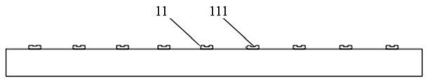
[0048] The busbar line 11 of the sliced battery 1 is engraved with a U-shaped notch 111 , and the U-shaped notch 111 is obtained by scribing along the center line of the busbar 11 through a non-destructive technique, and the scribed width is smaller than the minimum width of the busbar 11 , the depth is less than the height of the busbar 11;
[0049] The front busbars and the rear busbars of adjacent sliced cells 1 in each string of cells are connected by grid wire bonding tapes 2;
[0050] Before connecting, apply conductive glue 3 at the opening of U-shaped groove 111 of main grid line 11, and place adhesive film gasket 4 at the angle between grid line wel...
Embodiment 2
[0059] On the basis of the above photovoltaic components, the second embodiment of the present application provides a packaging method for photovoltaic components, including the following process flow:
[0060] Place the large-sized battery horizontally, and cut the large-sized battery into several sliced batteries 1 of the same size using laser or other non-destructive cutting technology along the direction parallel to the fine grid of the battery;
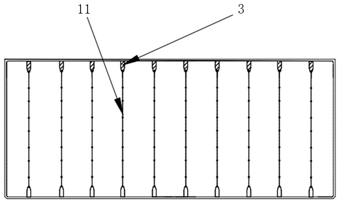
[0061] The busbar line 11 of the sliced battery 1 is scribed, and laser or other non-destructive techniques are used to scribe a width smaller than the minimum width of the busbar line 11 and a depth smaller than the height of the busbar line 11 along the center line of the busbar line of the sliced battery 1 . U-shaped notch 111; sliced battery 1 after scribing figure 2 shown;
[0062] Apply conductive adhesive 3 to the opening of the U-shaped groove 111 to ensure that the conductive adhesive 3 completely covers the op...
PUM
 Abstract
Description
Claims
Application Information
 - R&D
- Intellectual Property
- Life Sciences
- Materials
- Tech Scout
- Unparalleled Data Quality
- Higher Quality Content
- 60% Fewer Hallucinations
Browse by: Latest US Patents, China's latest patents, Technical Efficacy Thesaurus, Application Domain, Technology Topic, Popular Technical Reports.
© 2025 PatSnap. All rights reserved.Legal|Privacy policy|Modern Slavery Act Transparency Statement|Sitemap|About US| Contact US: help@patsnap.com