Phototherapy device for preventing and controlling myopia

A technology of prevention and control and phototherapy, applied in phototherapy, optics, ophthalmology treatment, etc., can solve problems such as macular damage and macular degeneration, and achieve the effects of preventing lesions, preventing and controlling myopia, and reducing oppression

Active Publication Date: 2022-06-21
AUTEK CHINA
View PDF3 Cites 2 Cited by
  • Summary
  • Abstract
  • Description
  • Claims
  • Application Information

AI Technical Summary

Problems solved by technology

The existing myopia prevention and control phototherapy device is to irradiate the whole eyeball with light emitted by the light source to achieve treatment. Since

Method used


Image

  • Phototherapy device for preventing and controlling myopia
  • Phototherapy device for preventing and controlling myopia
  • Phototherapy device for preventing and controlling myopia

Examples


Example Embodiment

[0037] Example 1.

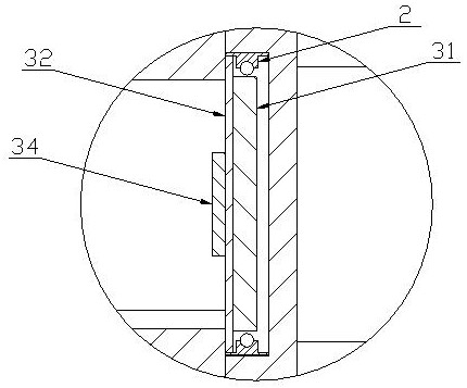
[0038] like Figure 4As shown, the diffuser plate 32 of the phototherapy device for myopia prevention and control is provided with a shielding plate 34 at the position corresponding to the macula of the patient's eyeball. Any of the lenses, painted lenses, opaque injection molded parts and opaque metal parts. By disposing a shielding plate 34 on the diffuser plate 32 to prevent light from irradiating the macula at the bottom of the patient's eyeball, the macula, which is more sensitive to light, is prevented from being directly irradiated, which can prevent damage to the macula during long-term use of the phototherapy device for myopia prevention and control.

Example Embodiment

[0039] Example 2.

[0040] A reflection grating is provided on the diffuser plate 32 of the phototherapy device for myopia prevention and control at a position corresponding to the macula of the patient's eyeball. Embodiment 2 replaces the shielding plate 34 in Embodiment 1 with a reflection grating, which can reflect most of the light directed to the macula at the bottom of the patient's eye back, thereby reducing the energy of the light directed to the macula at the bottom of the patient's eyeball.

Example Embodiment

[0041] Example 3.

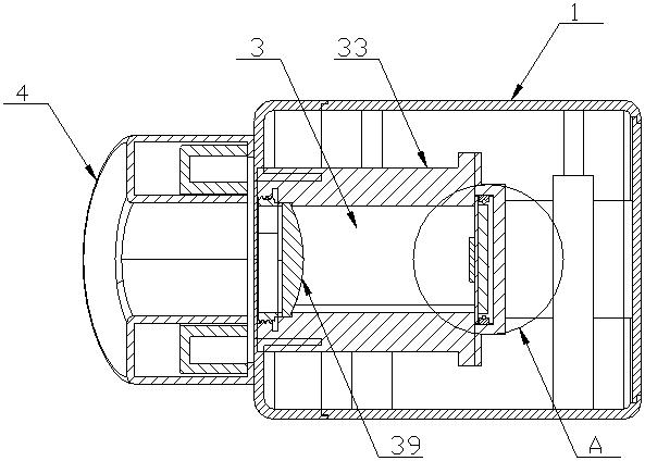
[0042] Figure 5 It is a schematic diagram of the optical path of the concave lens of the phototherapy device for myopia prevention and control provided by the embodiment of the present invention. like Figure 5 As shown, a concave lens 35 is arranged in the light barrel 33 of the light therapy device for myopia prevention and control, and the concave lens 35 is used for diffusing the light emitted from the diffusion plate 32 . The macula is usually located near the center of the bottom of the eyeball. By arranging the concave lens 35 in the light tube 33, the light can be diffused from the center, and the light energy in the center area can be reduced.


PUM


Abstract

The invention relates to the technical field of myopia prevention and control, in particular to a phototherapy device for myopia prevention and control, which comprises a shell, a light source and a light path module are arranged in the shell, and light emitted by the light source passes through the light path module and then is emitted to the macular position of eyeballs of a patient is weakened. Light emitted by the light source is projected to the retina through the light path module, blood flow and blood supply are increased after the choroid below the retina is irradiated by the red light with proper intensity, the original atrophic choroid and retina are restored, sclera hypoxia is fully supplemented, and therefore myopia is effectively prevented and controlled. Meanwhile, as choroid distribution at the macular position is denser than that of other parts and is more sensitive to light, the light path module is designed in a targeted manner, and energy of light emitted to the macular of the eyeball of the patient is weakened through different modes such as shielding, scattering, reflection and distribution of light guide points, so that the treatment effect of the macular macular is improved. Damage and calcification to macules in the process of using the phototherapy device for myopia prevention and control for a long time are avoided.

Description

technical field [0001] The invention relates to the technical field of myopia prevention and control, in particular to a phototherapy device for myopia prevention and control. Background technique [0002] Studies have shown that dopamine, as an important neurotransmitter on the retina, plays an important role in inhibiting the development of myopia. During the process of myopia, the homeostasis of retinal dopamine D1 receptors and D2 receptors is affected. During distance work-induced myopia, reduced choroidal blood supply causes scleral hypoxia, which is a key trigger for extracellular matrix remodeling during myopia development. Based on the above findings, we propose a systematic model for the pathogenesis of myopia: the out-of-focus signal of close working disrupts retinal dopamine receptor homeostasis, causing a decrease in choroidal blood supply leading to scleral hypoxia, which reduces scleral collagen, which in turn causes scleral extracellular Matrix remodeling, a...

Claims


Application Information

Patent Timeline
IPC IPC(8): A61N5/06A61F9/00G02B27/09
CPCA61N5/06A61F9/00G02B27/09
Inventor 陶悦群许攀吴端祥付志英李平侠杨西男刘通
Owner AUTEK CHINA
Why Eureka
Try Eureka