Lubricating and oiling equipment for mechanical equipment parts
A technology of mechanical equipment and oiling equipment, which is applied in the direction of mechanical equipment, lubricating parts, lubricating oil containers, etc., can solve the problems of unfavorable mechanical equipment normal operation, time-consuming and labor-intensive waste of grease, etc., and achieve the effect of saving manpower
Pending Publication Date: 2022-06-21
安徽耀达电机股份有限公司
View PDF0 Cites 2 Cited by
- Summary
- Abstract
- Description
- Claims
- Application Information
AI Technical Summary
Problems solved by technology
[0003] However, since the lubricating grease is sticky, the grease is often tightly adhered to the inner wall of the oil storage barrel. The existing lubrication and oiling equipment does not have the function of self-cleaning the adhered grease, and often needs to be manually disassembled and cleaned manually, which is time-consuming It is laborious, wastes grease, and if it is not cleaned for a long time, the grease will deteriorate, which is not conducive to the normal operation of mechanical equipment. Therefore, it is urgent to design a lubricating and oiling equipment for mechanical equipment parts to solve the above problems
Method used
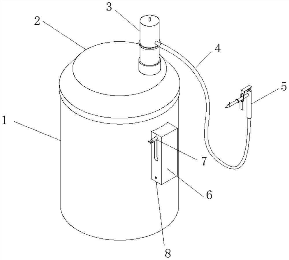
View moreImage
Smart ImageViewing Examples
Examples
Embodiment Construction
Login to View More PUM
 Abstract
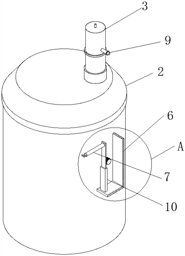
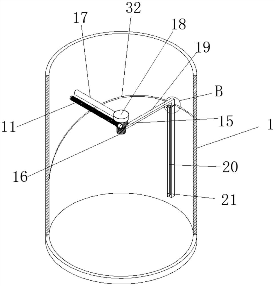
The invention provides lubricating and oiling equipment for mechanical equipment parts. The lubricating and oiling equipment is novel in structural design. Comprising a barrel body, a barrel cover covers the upper end of the barrel body, a pump head is vertically fixed to one side of the upper portion of the barrel cover through bolts, an oil gun is inserted into the end, away from the pump head, of a high-pressure oil pipe, an L-shaped scraper is horizontally welded to the lower portion of one side of a tooth column, and a strip-shaped through groove is vertically formed in the side, away from a gear, of the L-shaped scraper in the length direction of the L-shaped scraper. By means of the oil gun containing frame, attached grease can be effectively scraped and reused, the phenomenon that the grease is attached to the barrel wall for a long time and goes bad and expires is avoided, the oil gun containing frame is used for containing the oil gun, the oil gun containing frame is used for containing the oil gun, and the oil gun containing frame is convenient to use. The operation habit of people is met, the scraper is separated from the surface of the L-shaped scraper when ascending, and the situation that grease is scraped back to the upper end of the L-shaped scraper when the scraper moves upwards is avoided.
Description
technical field [0001] The invention relates to the technical field of oiling machines, in particular to a lubricating and oiling equipment for parts of mechanical equipment. Background technique [0002] Lubricating and oiling equipment is mainly used to transport lubricating oil in the lubrication system of various mechanical equipment. According to the driving mode, it is divided into pneumatic oiling machine, hydraulic oiling machine, manual oiling machine and motor-driven oiling machine. The products are widely used in CNC machinery, processing Center, elevator, production line, machine tool, forging, casting, textile, plastic, woodworking, rubber, mining, metallurgy, construction, printing, food and other industries of mechanical equipment lubrication system and automobile chassis centralized lubrication system. [0003] However, since the lubricating grease is sticky, the grease is often tightly adhered to the inner wall of the oil storage barrel. The existing lubrica...
Claims
Login to View More Application Information
Patent Timeline
 Patent Type & Authority Applications(China)
IPC IPC(8): F16N5/00F16N19/00B08B9/08B08B9/087B08B1/00B08B1/02B08B1/20
CPCF16N5/00F16N19/00B08B9/0808B08B1/20B08B1/165
Inventor 左顺伍汪学兵王波汪良益
Owner 安徽耀达电机股份有限公司
Features
- R&D
- Intellectual Property
- Life Sciences
- Materials
- Tech Scout
- Unparalleled Data Quality
- Higher Quality Content
- 60% Fewer Hallucinations
Learn More Browse by: Latest US Patents, China's latest patents, Technical Efficacy Thesaurus, Application Domain, Technology Topic, Popular Technical Reports.
© 2025 PatSnap. All rights reserved.Legal|Privacy policy|Modern Slavery Act Transparency Statement|Sitemap|About US| Contact US: help@patsnap.com


