Wave absorber and preparation method thereof
A wave absorber and metal sheet technology, applied in antennas, electrical components, etc., can solve the problems of large size, poor wave absorption performance, narrow wave absorption bandwidth, etc., to achieve wide wave absorption bandwidth, excellent wave absorption performance, and reduce production. cost effect
- Summary
- Abstract
- Description
- Claims
- Application Information
AI Technical Summary
Problems solved by technology
Method used
Image
Examples
no. 1 example
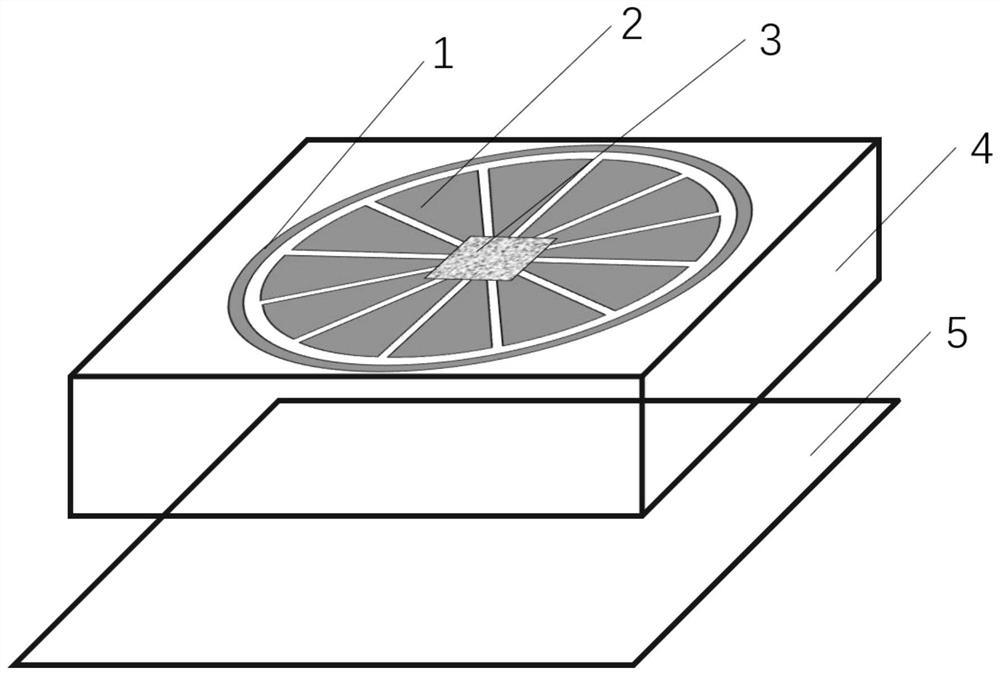
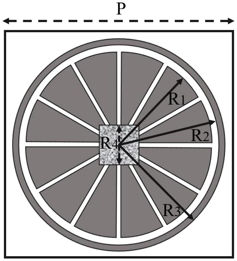
[0035] Please refer to figure 1 , which is a schematic structural diagram of an embodiment of the wave absorber of the present application. In this embodiment, the wave absorber includes: at least one metal patch, and the metal patch includes: an annular metal sheet 1 located on the outer layer, and a plurality of annular metal sheets located in the annular metal sheet 1 Petal metal sheet 2. The wave absorber also includes: at least one resistive film 3 , a dielectric layer 4 and a metal base plate 5 .
[0036] The metal patch, the resistive film 3, the dielectric layer 4 and the metal base plate 5 are arranged in order from top to bottom. The metal patch and the resistive film 3 constitute the absorber surface structure. The metal patch covers the surface of the dielectric layer 4 , and the resistive film 3 can be placed in the metal patch to form electrical communication with the plurality of petal-shaped metal sheets 2 . The backside of the dielectric layer 4 is attache...
no. 2 example
[0050] In the above-mentioned embodiment, a wave absorber is provided, and correspondingly, the present application also provides a preparation method of the wave absorber. The method corresponds to the embodiment of the above-mentioned product. Since the method embodiment is basically similar to the product embodiment, the description is relatively simple, and the relevant part may refer to the partial description of the product embodiment. The method embodiments described below are merely illustrative.
[0051] The application additionally provides a method for preparing a wave absorber, comprising:
[0052] Step 1: cover the surface of the dielectric layer with a metal patch by a metal etching process, the metal patch includes: a ring-shaped metal sheet, and a plurality of petal-shaped metal sheets placed in an annular shape in the ring-shaped metal sheet;
[0053] Step 2: connecting the resistive film and the plurality of petal-shaped metal sheets to form electrical comm...
no. 3 example
[0057] In the above-mentioned embodiment, a wave absorber is provided, and correspondingly, the present application also provides a radio frequency identification system. The radio frequency identification system corresponds to the above-mentioned embodiment of the wave absorber. Since the system embodiment is basically similar to the product embodiment, the description is relatively simple, and the relevant part may refer to the partial description of the product embodiment. The system embodiments described below are merely illustrative.
[0058] The present application further provides a radio frequency identification system, comprising: the above-mentioned wave absorber, in addition to an RFID reader, and an electronic tag. RFID reader, namely radio frequency identification technology, this technology is usually used for wireless transmission and reception. RFID readers are widely used in various fields, such as: manufacturing, logistics, ports, docks, vehicles and person...
PUM
 Abstract
Description
Claims
Application Information
 - R&D
- Intellectual Property
- Life Sciences
- Materials
- Tech Scout
- Unparalleled Data Quality
- Higher Quality Content
- 60% Fewer Hallucinations
Browse by: Latest US Patents, China's latest patents, Technical Efficacy Thesaurus, Application Domain, Technology Topic, Popular Technical Reports.
© 2025 PatSnap. All rights reserved.Legal|Privacy policy|Modern Slavery Act Transparency Statement|Sitemap|About US| Contact US: help@patsnap.com


