
High-frequency time-division multi-target microwave wireless energy transmission system

A microwave wireless and energy transmission technology, applied in the direction of circuit devices, electrical components, etc., can solve the problems of complex structure, small power capacity and high cost of multi-target radiation systems, and achieve easy improvement and upgrade, large power capacity and simple structure Effect

Pending Publication Date: 2022-06-24
NANJING UNIV OF AERONAUTICS & ASTRONAUTICS
View PDF0 Cites 0 Cited by
  • Summary
  • Abstract
  • Description
  • Claims
  • Application Information

AI Technical Summary

Problems solved by technology

[0005] In order to make up for the various deficiencies of the above-mentioned background technology, the present invention proposes a high-frequency time-division multi-target microwave wireless energy transmission system based on time-division multi-beam technology, starting from reducing system complexity and improving the real-time performance and stability of energy transmission. By switching the radiation direction of the energy beam at high frequency to simultaneously supply energy to at least one energy-receiving target, it can fully meet the demand of simultaneous energy transfer to multiple targets, which is more practical and solves the problem of complex structure and high cost of the existing multi-target radiation system. The power capacity is small and the efficiency is extremely low, so it is difficult to apply to practical technical problems

Method used


Image

  • High-frequency time-division multi-target microwave wireless energy transmission system
  • High-frequency time-division multi-target microwave wireless energy transmission system
  • High-frequency time-division multi-target microwave wireless energy transmission system

Examples


Embodiment Construction

[0033] The technical solutions of the invention will be described in detail below with reference to the accompanying drawings.

[0034] figure 2 The system block diagram of the high-frequency time-division multi-target microwave wireless energy transmission system proposed by the present invention is shown. In order to clarify its specific realization principle, the application of the phased array technology in the present invention is briefly introduced first.

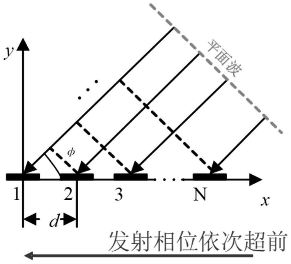
[0035] Taking a one-dimensional linear antenna array as an example, the arrangement of the antenna elements is shown in Figure 1(b). Assuming that the array consists of n elements arranged in a straight line, where n is any positive integer and the element spacing is d, the total phase difference between two adjacent elements and the feed phase difference And the relationship of beam pointing φ can be expressed as:

[0036]

[0037] where k=2π / 2. Taking antenna 1 as a reference, the electric field phase differe...


PUM


Abstract

The invention discloses a high-frequency time-division multi-target microwave wireless energy transmission system, relates to a microwave wireless energy transmission and phased array multi-target directional radiation technology, and belongs to the technical field of power generation, power transformation or power distribution. According to the method, a multi-target microwave wireless energy transmission system which is simple and easy to use and transmits energy to multiple targets at the same time is provided based on a phased array directional radiation technology, and a high-frequency control signal is used for forcibly switching beam angles on the basis of realizing respective directional radiation on a single target; in addition, the invention discloses a power transmitting and distributing algorithm based on the hardware transmitting scheme, required power is accurately provided for each energy receiving target, and each energy receiving target simultaneously receives stable direct-current voltage with the required power in a time domain by using a specially-designed filter. The scheme provided by the invention has the advantages of simple and easy-to-implement control structure, good directional radiation effect, high transmission efficiency and the like.

Description

technical field [0001] The invention discloses a high-frequency time-division multi-target microwave wireless energy transmission system, which relates to microwave wireless energy transmission and phased array multi-target directional radiation technology, and belongs to the technical field of power generation, transformation or distribution. Background technique [0002] Microwave wireless energy transmission (MPT, Microwave Power Transmission) uses electromagnetic waves as the energy transmission carrier to achieve directional wireless transmission of energy. It is less affected by climate and has a long transmission distance, and can transmit high-power energy to a single target (such as drones). , and can quickly transmit energy to multiple targets at the same time (such as notebook computers, mobile phones, headphones, etc.), and can realize full-coverage real-time wireless energy transmission of point-to-point and point-to-body in complex environments. The excellent o...

Claims


Application Information

Patent Timeline
IPC IPC(8): H02J50/20H02J50/40H02J50/80
CPCH02J50/20H02J50/402H02J50/80
Inventor 金科程舒晨胡欢
Owner NANJING UNIV OF AERONAUTICS & ASTRONAUTICS
Learn More