
Ocean vessel wind energy air water generator

An air-to-water machine and air-to-water technology, which are applied in wind power generation, wind turbines, wind turbine combinations, etc., can solve the problems of difficult construction, high cost, low cost, etc., and achieve reasonable structural design, high compression efficiency, and Water efficient effect

Pending Publication Date: 2022-06-28
CHANGZHOU UNIV
View PDF0 Cites 0 Cited by
  • Summary
  • Abstract
  • Description
  • Claims
  • Application Information

AI Technical Summary

Problems solved by technology

There are generally two methods of water supply for ocean-going ships today. One is to replenish water on land. However, if you are traveling on the ocean for a long time, you need a lot of water resources. These water resources not only occupy a certain volume of ocean-going ships, but also have relatively large quality
The second is the seawater desalination device, which is not only expensive, but also consumes energy on ocean-going ships
The biggest problem with this method is: the vertical pipe needs to be built 100m or higher, and the diameter needs to be very large. The actual construction is difficult and the cost is high.
Fog-gathering water extraction method is low in cost and high in efficiency, and has applications in many fields, but it is limited by the environment and is only suitable for promotion in water-deficient and foggy places
[0008] The existing air water production methods and devices and the requirements for air conditions cannot meet the water production needs of ocean-going ships. Therefore, how to use offshore wind energy and air to condense water production has become the focus of design

Method used


Image

  • Ocean vessel wind energy air water generator
  • Ocean vessel wind energy air water generator
  • Ocean vessel wind energy air water generator

Examples


Embodiment Construction

[0024] The present invention will now be described in further detail with reference to the accompanying drawings. These drawings are all simplified schematic diagrams, and only illustrate the basic structure of the present invention in a schematic way, so they only show the structures related to the present invention, and the directions and references (eg, up, down, left, right, etc.) may only be Used to aid in the description of features in the drawings. Therefore, the following detailed description is not to be taken in a limiting sense, and the scope of the claimed subject matter is defined solely by the appended claims and their equivalents.

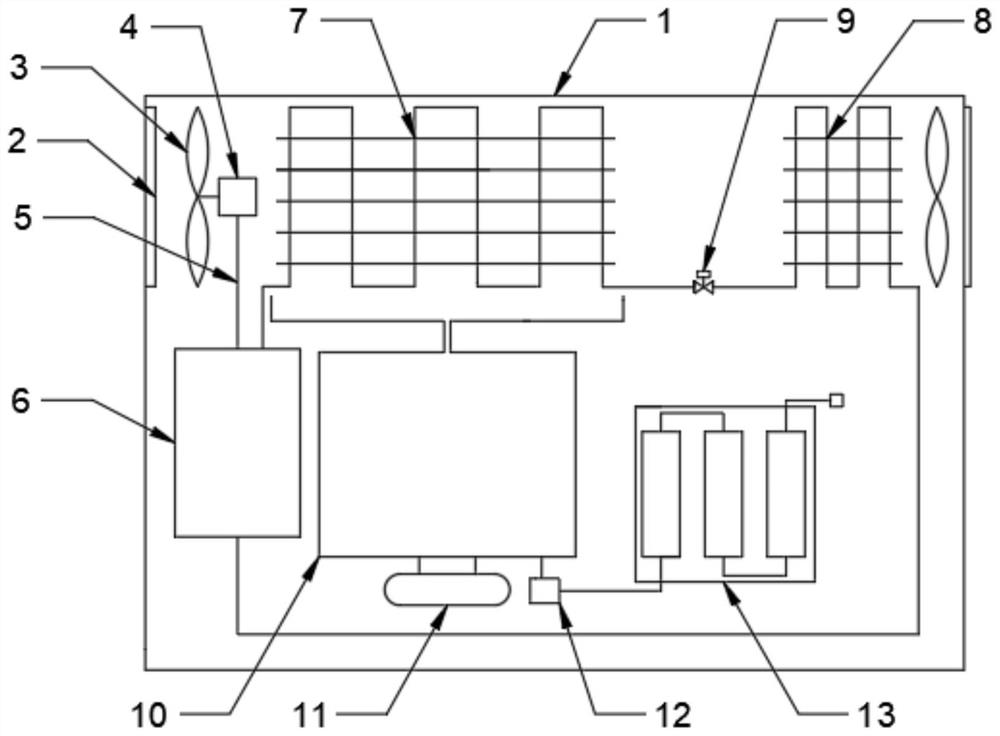
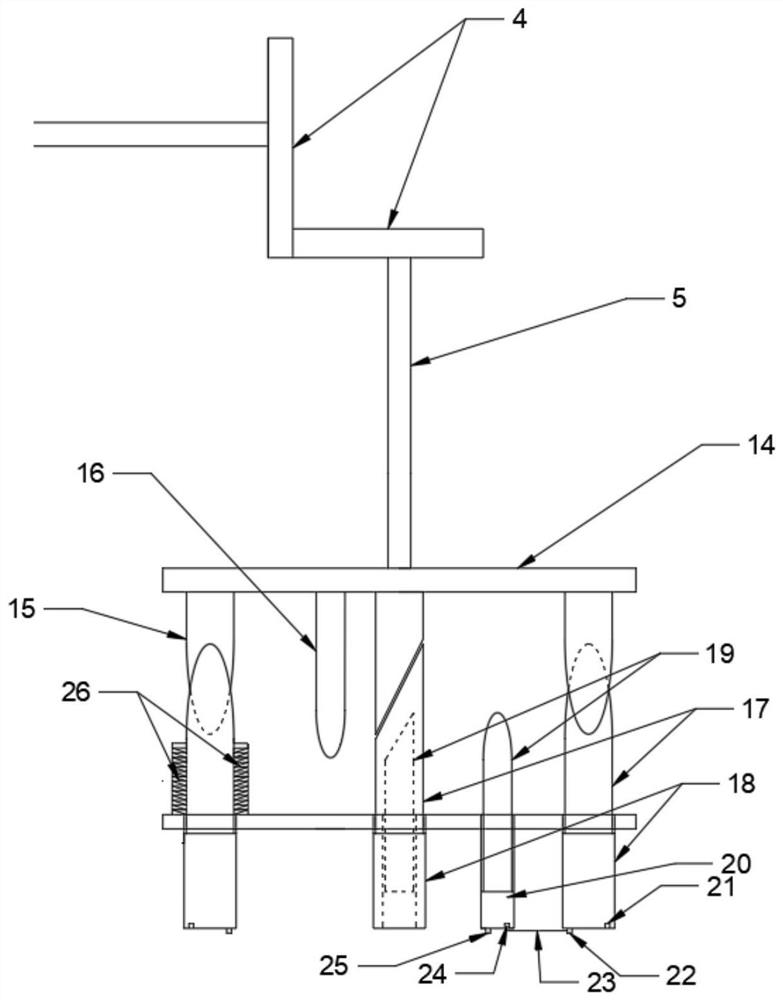
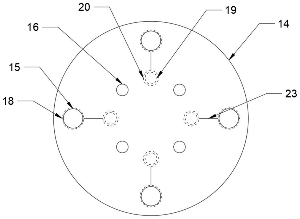
[0025] like figure 1 An ocean-going ship wind energy air water maker is shown, which is the best embodiment of the present invention. The ocean-going ship wind energy air water maker includes a casing 1, a wind wheel 3, a mechanical transmission mechanism 4 and an air water maker. The casing 1 is provided with an air inlet 2 on one ...


PUM


Abstract

The invention provides a wind energy air water generator for an ocean vessel. The wind energy air water generator comprises a wind wheel, a mechanical transmission mechanism and an air water generation mechanism, the air water making mechanism comprises a compression mechanism, a condenser and an evaporator, and a water tank is arranged below the evaporator. The air water generator is reasonable in structural design, wind power resources on the ocean serve as an active air supply system to provide energy for the air water generator, wind energy on the ocean can be directly utilized, and even if the ocean vessel is still on the sea surface, large wind power resources on the ocean can be directly utilized. Meanwhile, the wind energy system can be directly utilized without converting electric energy, mechanical energy converted by wind energy is directly utilized to serve as energy supply of the compression mechanism, loss of energy conversion is greatly reduced, the correspondingly designed compression mechanism can normally operate through a mechanical structure driven by the wind energy, the compression efficiency is high, and the compression efficiency is high. Sufficient power is provided for refrigerants in the whole refrigerating system, so that the refrigerants flow faster, the cooling water production effect is good, and the water production efficiency is high.

Description

technical field [0001] The invention relates to the technical field of wind energy utilization, in particular to an ocean-going ship wind energy air water maker. Background technique [0002] Ocean-going ships travel on the ocean for a long time, and it is difficult to obtain food and drinking water supplies for a long time. The crew of ocean-going ships not only face the problem of lack of water and drinking water, but also sometimes the quality of drinking water. There are generally two water supply methods for ocean-going ships. One is to replenish water on land. However, if it is to drive on the ocean for a long time, it requires a lot of water resources. These water resources not only occupy a certain volume of ocean-going ships, but also have a large amount of water. quality. The second is the seawater desalination device, which is not only expensive, but also consumes energy on ocean-going ships. However, there are more freshwater resources in the air above the ocea...

Claims


Application Information

Patent Timeline
Patent Type & Authority Applications(China)
IPC IPC(8): E03B3/28F03D9/28
CPCE03B3/28F03D9/28Y02E10/72
Inventor 王金良李明珅武家楼
Owner CHANGZHOU UNIV
Learn More