
Punching shear punching machine tool with cutter convenient to replace

A punching machine tool and punching mechanism technology, applied in the field of punching and shearing punching machines, can solve problems affecting work efficiency, inconvenient tool replacement, etc., and achieve the effect of improving processing efficiency and speed of switching

Active Publication Date: 2022-07-01
南通博晟威机械有限公司
View PDF7 Cites 0 Cited by
  • Summary
  • Abstract
  • Description
  • Claims
  • Application Information

AI Technical Summary

Problems solved by technology

[0004] The purpose of the present invention is to provide a punching, shearing and stamping machine tool that is convenient for tool replacement, so as to solve the problem that it is inconvenient to replace the tools for punching and shearing different workpieces on the punching, shearing and stamping machine tool proposed in the background technology above, which affects work efficiency.

Method used


Image

  • Punching shear punching machine tool with cutter convenient to replace
  • Punching shear punching machine tool with cutter convenient to replace
  • Punching shear punching machine tool with cutter convenient to replace

Examples


Embodiment Construction

[0031] The technical solutions in the embodiments of the present invention will be clearly and completely described below with reference to the accompanying drawings in the embodiments of the present invention. Obviously, the described embodiments are only a part of the embodiments of the present invention, but not all of the embodiments. Based on the embodiments of the present invention, all other embodiments obtained by those of ordinary skill in the art without creative efforts shall fall within the protection scope of the present invention.

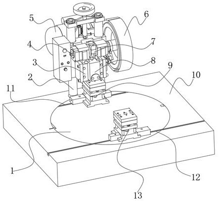
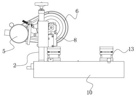
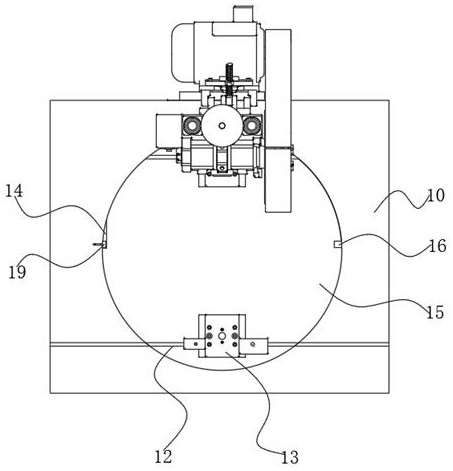
[0032] see Figure 1-Figure 9 , The present invention provides a technical solution: a punching, shearing and punching machine tool that is convenient for changing tools, including a tool switching base mechanism 1 and a fixed seat 10, and the fixed seat 10 is provided with a tool switching base mechanism 1 for switching tools. The upper end of 10 is provided with a punching and shearing punching mechanism;

[0033] The punching and ...


PUM


Abstract

The invention discloses a punching, shearing and punching machine tool convenient to replace cutters, the punching, shearing and punching machine tool comprises a cutter switching base mechanism and a fixing seat, the cutter switching base mechanism used for switching the cutters is arranged in the fixing seat, and a punching, shearing and punching mechanism is arranged at the upper end of the fixing seat. Cutter sets on the punching and shearing machine tool can be conveniently switched for use, when a machining cutter needs to be replaced, a pressing plate on the first cutter set moves downwards to compress a reset spring to be shrunk, the pressing plate is separated from a limiting block, a rotating motor is started to drive a fixed gear to rotate anticlockwise, and the machining cutter can be replaced. The fixed gear drives the toothed plate in the inner ring to rotate clockwise, the toothed plate drives the rotating base at the upper end to rotate clockwise, due to the limiting effect of the clamping block in the inclined groove, the cutters on the machine tool are switched through the method, the cutter switching speed can be greatly increased, and the machining and using efficiency is improved.

Description

technical field [0001] The invention belongs to the related technical field of punching, shearing and punching machines, and in particular relates to a punching, shearing and punching machine tool which is convenient for changing cutters. Background technique [0002] Punching and shearing punching machine is a kind of shearing or punching equipment on the roller line. According to the different tools installed, it can be used to cut the sheet to the required length, or to emboss the sheet. In modern flexible production lines, a Roller lines often need to produce profiles of 2 or 3 specifications. Generally, the profile specifications need to be changed once every one to two days. In this way, the knives on the punching and shearing punching machine need to be replaced frequently. The knife and the moving knife are used together. Before working, the punching and shearing punching machine can move back and forth along the conveying direction of the production line to adjust t...

Claims


Application Information

Patent Timeline
Patent Type & Authority Applications(China)
IPC IPC(8): B21D37/06
CPCB21D37/06
Inventor 石崇
Owner 南通博晟威机械有限公司
Learn More