
Charge pump circuit

A technology of charge pump and circuit, which is applied in the direction of electrical components, adjustment of electric variables, output power conversion devices, etc., can solve problems such as transistor damage, and achieve the effect of avoiding peak current

Pending Publication Date: 2022-07-01
SG MICRO
View PDF0 Cites 0 Cited by
  • Summary
  • Abstract
  • Description
  • Claims
  • Application Information

AI Technical Summary

Problems solved by technology

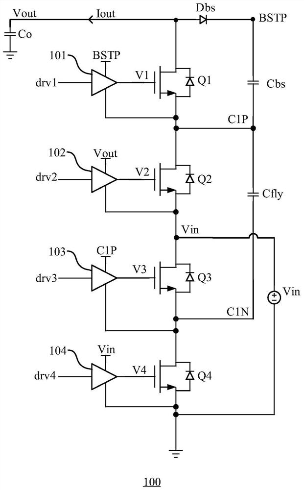
[0008] In order to solve the above technical problems, the present disclosure provides a charge pump circuit, which can improve the problem of damage to the transistor caused by excessively high peak current flowing through the body diode of the transistor when the charge pump circuit is soft-started, and improve circuit reliability.

Method used


Image

  • Charge pump circuit
  • Charge pump circuit
  • Charge pump circuit

Examples


Embodiment Construction

[0043] In order to facilitate understanding of the present disclosure, the present disclosure will be described more fully hereinafter with reference to the related drawings. Preferred embodiments of the present disclosure are shown in the accompanying drawings. However, the present disclosure may be embodied in different forms and is not limited to the embodiments described herein. Rather, these embodiments are provided so that a thorough and complete understanding of the present disclosure is provided.

[0044] It should be understood that in the following description, "circuitry" may include single or multiple combined hardware circuits, programmable circuits, state machine circuits, and / or elements capable of storing instructions executed by the programmable circuits. When an element or circuit is referred to as being "connected" to another element or an element / circuit is "connected" between two nodes, it may be directly coupled or connected to the other element or inter...


PUM


Abstract

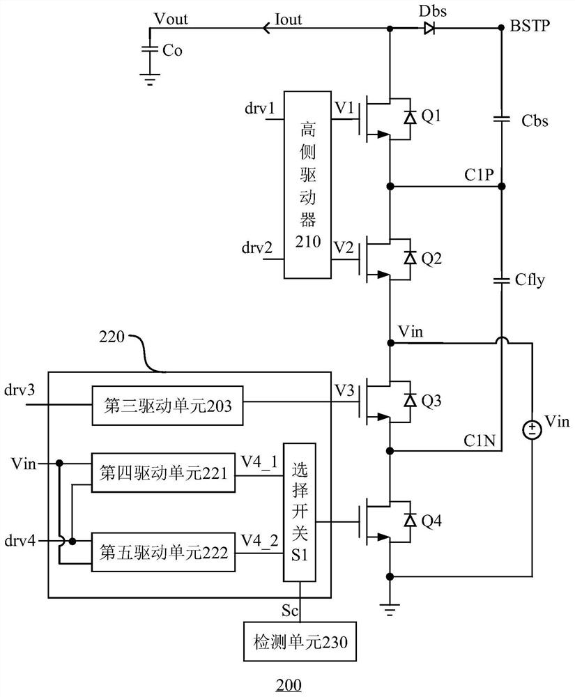
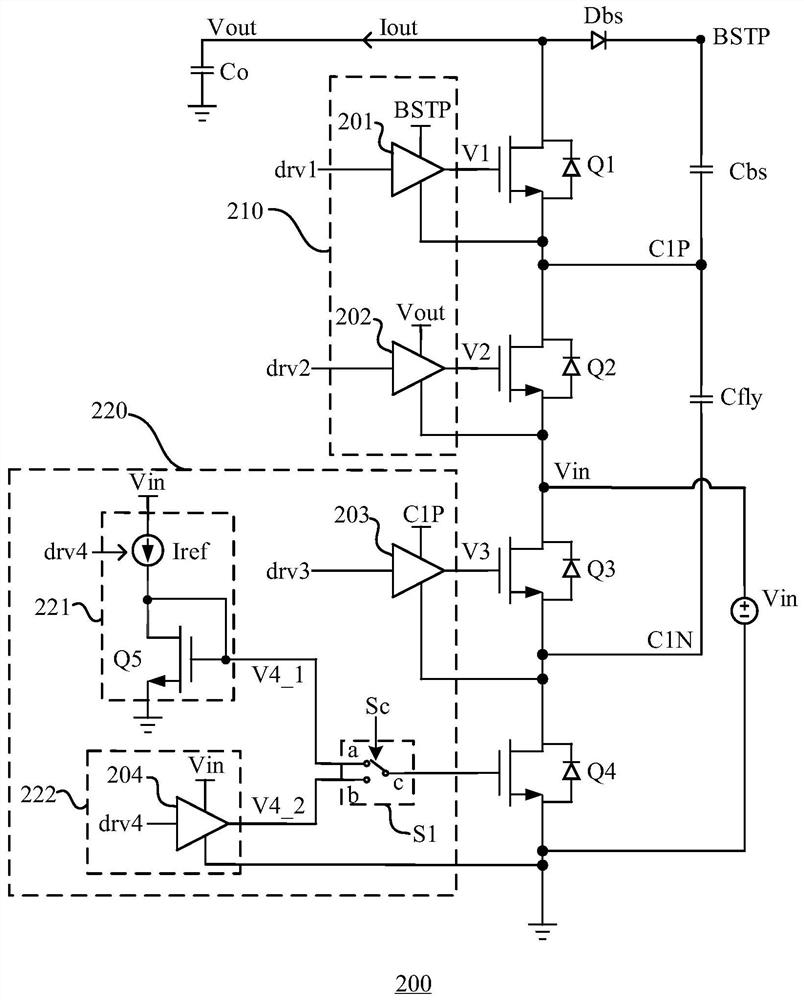
The invention relates to the technical field of power converters, and provides a charge pump circuit, which is characterized in that a first transistor and a second transistor are respectively controlled to be switched on and switched off in a complementary manner in each clock period by using a high-side driver, and an output current is provided at a voltage output end of the charge pump circuit; a low-side driver is used for respectively controlling the third transistor and the fourth transistor to be switched on and switched off in a complementary mode in each clock period during the soft start period of the charge pump circuit so as to be matched with the second transistor to charge the flying capacitor or matched with the flying capacitor to discharge the voltage output end through the first transistor; and the magnitude of the charging current on the flying capacitor is controlled in a clamping mode so as to adjust the voltage difference between the two ends of the first transistor when the voltage output end is discharged. Therefore, the problem that the transistor is damaged due to the fact that current with an overhigh peak flows through the body diode of the transistor during soft start of the charge pump circuit in the prior art can be solved, and the reliability of the circuit is improved.

Description

technical field [0001] The present disclosure relates to the technical field of power converters, and in particular, to a charge pump circuit. Background technique [0002] A charge pump, also known as a switched-load capacitive voltage converter, is a converter that utilizes a so-called "fast" or "pumping" load capacitance to store energy. The charge pump can be configured to generate an output voltage that is a multiple of the input voltage (eg, 2, 3...N times), or it can set an output voltage that is a fraction of it (eg, 1 / 2, 1 / 3...1 / N times the input voltage). In some implementations, this circuit can also generate a negative output voltage from a positive input voltage. Because charge pump circuits do not require inductors for voltage conversion, they are sometimes called inductorless DC / DC converters and are widely used in power supplies, memory, and radio frequency chips. [0003] Compared with the traditional inductive switching power supply, the DC / DC converter...

Claims


Application Information

Patent Timeline
Patent Type & Authority Applications(China)
IPC IPC(8): H02M3/158H02M1/34H02M1/088
CPCH02M3/158H02M1/34H02M1/088
Inventor 高峡谢云宁秦筝郭廷周元春
Owner SG MICRO
Learn More