Anti-corrosion treatment equipment in water conservancy project and working method of anti-corrosion treatment equipment

A technology for anti-corrosion treatment and water conservancy engineering. It is used in mechanical equipment, pipeline anti-corrosion/rust protection, damage protection, etc. It can solve problems such as difficulty in mechanical automatic brushing, aggravating the corrosion degree of metal water conservancy pipelines, and heavy workload.

Pending Publication Date: 2022-07-05
刘丹
View PDF0 Cites 0 Cited by
  • Summary
  • Abstract
  • Description
  • Claims
  • Application Information

AI Technical Summary

Problems solved by technology

[0003] In water conservancy projects, water conservancy pipelines play an important role. Water conservancy pipelines play the role of water resource transportation. Among them, the anticorrosion treatment technology of water conservancy pipelines has always been the research direction of technicians in the field. In recent years, the country has paid more and more attention to environmental protection issues. Coupled with the advantages of metal water conservancy pipelines such as safety and hygiene, health and environmental protection, long life, high temperature resistance and high pressure resistance, the proportion of metal water conservancy pipelines

Method used


Image

  • Anti-corrosion treatment equipment in water conservancy project and working method of anti-corrosion treatment equipment
  • Anti-corrosion treatment equipment in water conservancy project and working method of anti-corrosion treatment equipment
  • Anti-corrosion treatment equipment in water conservancy project and working method of anti-corrosion treatment equipment

Examples


no. 1 example

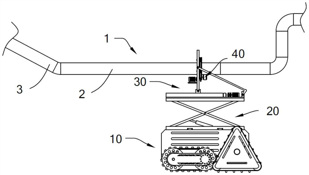
[0035] like Figure 1 to Figure 4 As shown, the present invention provides an anti-corrosion treatment equipment in a water conservancy project, including a moving vehicle 10 , a lifting assembly 20 , a dipping assembly 30 and a brushing unit 40 .

[0036] The lifting assembly 20 is arranged on the moving vehicle 10;

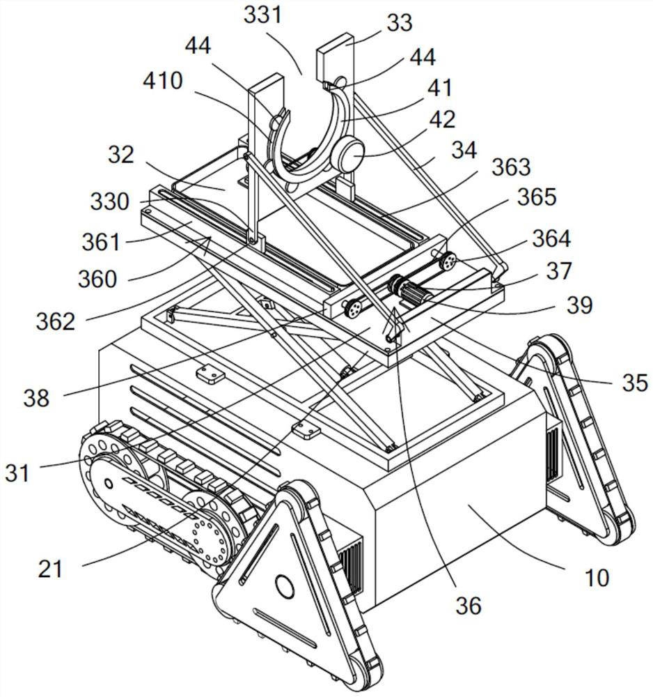
[0037] The dip assembly 30 includes a base plate 31, a dip frame 32, a flip plate 33, an L-shaped hinge rod 34, a mounting plate 35 and a drive unit 36. The base plate 31 is fixedly connected to the top of the lifting assembly 20, and the dip frame 32 is fixedly arranged on the base plate. 31, the mounting plate 35 is fixedly arranged on the base plate 31, and the mounting plate 35 is located at the front end of the dipping frame 32, the number of L-shaped hinge rods 34 is two, and one end of the two L-shaped hinge rods 34 is respectively connected with the mounting plate 35. Hinged, the other ends of the two L-shaped hinge rods 34 are hinged to the center positi...

no. 2 example

[0051] The driving unit 36 ​​includes a driving member 360, a driving wheel 37, a fixed plate 38 and a turning motor 39. The number of the driving members 360 is two. 364 and the conveyor belt 365, the two slideways 361 are fixedly arranged on the base plate 31, and the two slideways 361 are located on both sides of the dip frame 32, the mounting plate 35 is fixedly connected to the base plate 31, and the fixing plate 38 is located on the mounting plate 35 and the dipping frame 32, a lead screw 363 is arranged in the slideway 361 to rotate along its length direction, a slide block 362 is sleeved on the lead screw 363, the slide block 362 is hinged with the extension plate 330, and one end of the lead screw 363 is One end is fixedly connected, and the other end of the rotating shaft is fixedly connected to the driven wheel 364 through the fixed plate 38. The driven wheel 364 is connected to the driving wheel 37 through the conveyor belt 365. On the output shaft of the inversion...

no. 3 example

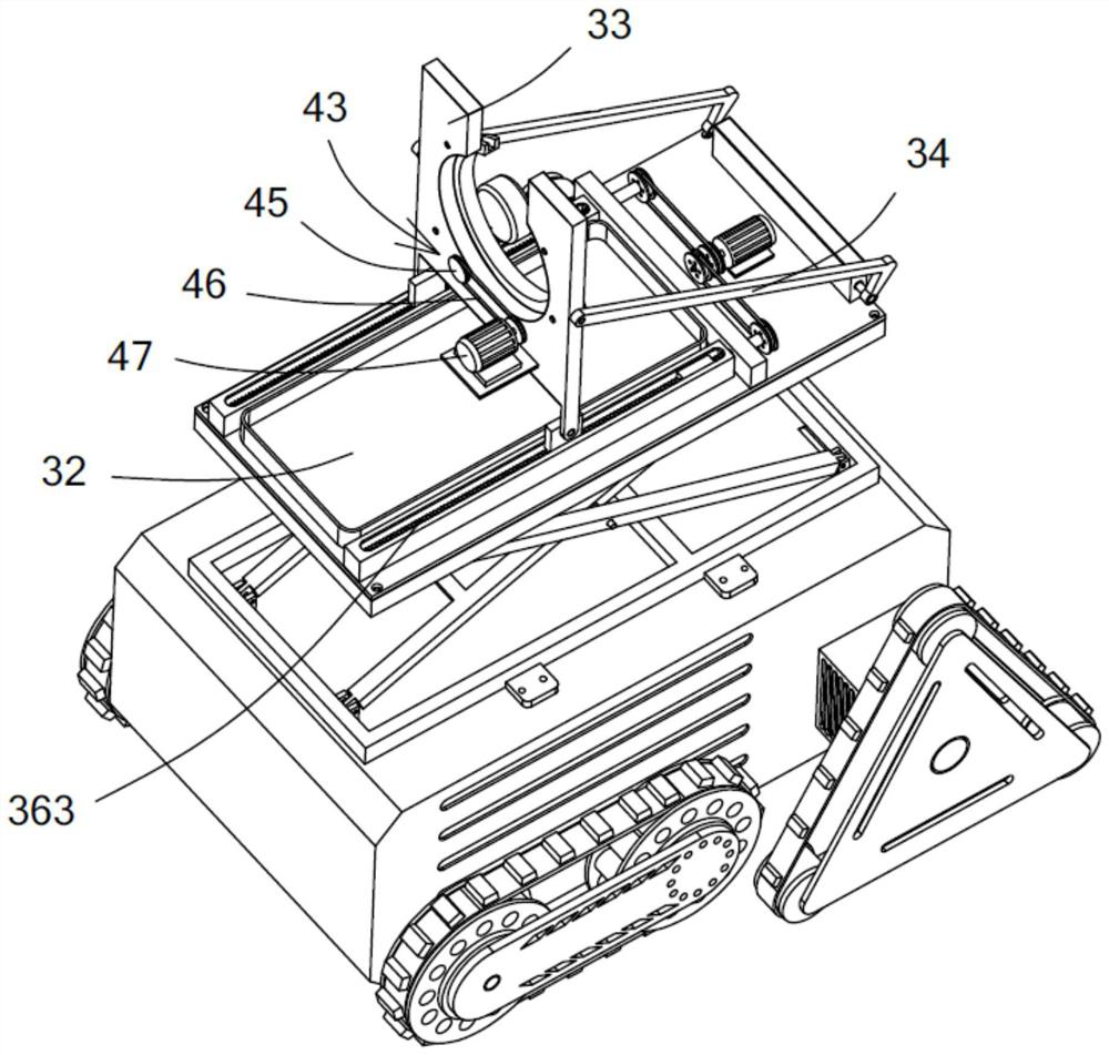
[0056] The brushing unit 40 also includes a transmission member 43, the transmission member 43 is used to drive the wheel frame 41 to rotate, the wheel frame 41 is a ring body, the outer ring wall of the ring body is provided with a guide groove 410, the ring body is provided with a second notch 44, and the transmission member 43 It includes a limit wheel 44, a transmission wheel 45, a transmission belt 46 and a transmission motor 47. There are multiple limit wheels 44, and the plurality of limit wheels 44 are rotated and arranged on one side wall of the flap 33. The number of the drive wheels 45 is two. The rotation of the two transmission wheels 45 is arranged on the other side wall of the flap 33 , and the two transmission wheels 45 are respectively linked with the two adjacent limit wheels 44 , and the transmission belt 46 is sleeved on the two transmission wheels 45 . , the output shaft of the transmission motor 47 is fixedly connected with any transmission wheel 45 , the ...


PUM


Abstract

The invention provides anti-corrosion treatment equipment in a water conservancy project. The anti-corrosion treatment equipment comprises a moving vehicle, a lifting assembly, a dipping assembly and a brushing unit. Firstly, the moving trolley moves to the position under the water conservancy pipeline to be brushed, the lifting assembly further drives the dipping assembly and the brushing unit to rise to the proper height, the turning plate is further away from the mounting plate and is parallel to the base plate, the automatic dipping action is achieved, the driving unit further drives the bottom end of the turning plate to move, and the turning plate is made to present different inclination angles; according to the water conservancy pipeline brushing device, the turning plate presents different inclination angles, the brushing action can be achieved aiming at different bent sections of the water conservancy pipeline, and when the turning plate is perpendicular to the base plate, the brushing action is achieved aiming at the horizontal section of the water conservancy pipeline, and automatic and mechanical water conservancy pipeline brushing is achieved aiming at the structures of the different sections of the water conservancy pipeline; the working efficiency is improved; and the labor cost is reduced.

Description

technical field [0001] The invention relates to an anti-corrosion treatment device in a water conservancy project and a working method thereof, in particular to an anti-corrosion treatment device for realizing automatic mechanization and a water conservancy pipeline in a water conservancy project and a working method thereof. Background technique [0002] Water is an indispensable resource in human production and life. It can be said that water directly affects people's clothing, food, housing, and transportation, but water in its natural state cannot fully meet people's needs. Water conservancy projects can solve this problem, and water conservancy projects are used for deployment and control. Natural groundwater and surface water. [0003] In water conservancy projects, water conservancy pipelines play an important role, and water conservancy pipelines play a role in the transportation of water resources. Among them, the anti-corrosion treatment technology of water conserv...

Claims


Application Information

Patent Timeline
IPC IPC(8): F16L58/02B66F7/06B66F7/08B05B13/02
CPCF16L58/02B66F7/065B66F7/08B66F7/0625B05B13/0207B05B13/0285Y02P70/10
Inventor 刘丹张京华
Owner 刘丹
Why Eureka
Try Eureka