Mobile flying direct air carbon dioxide trapping system and method

A carbon dioxide and air technology, applied in the field of carbon capture, can solve the problems of bulky and immobile devices, and achieve the effect of improving efficiency, reducing replacement time and high efficiency

Pending Publication Date: 2022-07-08
TIANJIN UNIV
View PDF6 Cites 0 Cited by
  • Summary
  • Abstract
  • Description
  • Claims
  • Application Information

AI Technical Summary

Problems solved by technology

[0005] The publication number is CN113856419A, and the invention patent titled "a carbon dioxide capture system and capture method" discloses a new carbon dioxide capture method and system, although the performance of the patent is compared with that of the alcohol used in the current coal-fired power plants. Amine solution chemisorption is better, but the device is bulky and cannot be moved

Method used


Image

  • Mobile flying direct air carbon dioxide trapping system and method
  • Mobile flying direct air carbon dioxide trapping system and method
  • Mobile flying direct air carbon dioxide trapping system and method

Examples


Embodiment 1

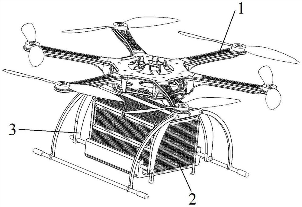
[0029] like Figures 1 to 5 As shown, the present embodiment provides a direct-air carbon dioxide capture system that can fly, including a capture-type flying device 1 and an adsorption device 2; the adsorption device 2 includes an adsorption box and a connecting mechanism 3; the adsorption box is used to hold the adsorption The connection mechanism 3 is used to connect with the capture-type flying device 1 , and the adsorption box is arranged on the connection mechanism 3 .

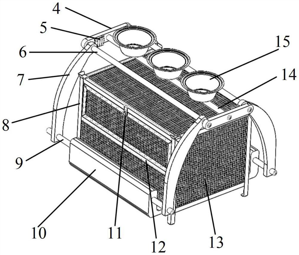
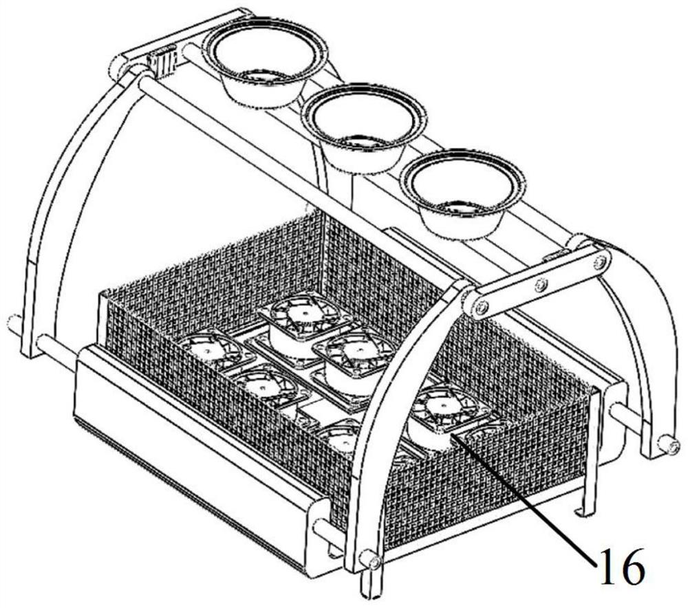
[0030]In this specific embodiment, the connecting mechanism 3 includes a connecting member 15, a hinge rod 4, a claw clip 7, a rotating rod 6, a support frame 10 and a motor; The two ends of the bottom are respectively connected with the middle of a hinge rod 4, the housing of the motor is connected with the end of the hinge rod 4, the output shaft of the motor is connected with the end of the rotating rod 6, the rotating rod 6 is connected with the top of the claw clamp 7 In connection, the support fra...

Embodiment 2

[0039] like Image 6 As shown, this embodiment provides a method based on the mobile direct air carbon dioxide capture system in the first embodiment, setting the flight trajectory according to the carbon dioxide emission satellite data or preset geographic information, and determining the transfer station in the calculation flight path. 25 settings to ensure that the farthest flight range can cover the carbon source target site with the assistance of the power supply of the transfer station 25; the observation-type flight device 17 flies and scouts within the detection range, and realizes the rapid carbon source according to the real-time monitoring data of the carbon dioxide optical detector. Positioning; the capture-type flight device 1 is equipped with an adsorption device 2 at the transfer station 25 and filled with energy, and flies out to each marked point on the parking pad 22 according to the three-dimensional position information of the carbon source, and captures car...


PUM


Abstract

The invention discloses a direct air carbon dioxide trapping system and method capable of moving and flying, and relates to the technical field of carbon trapping, and the system comprises a trapping type flying device and an adsorption device; the adsorption device comprises an adsorption box and a connecting mechanism; the adsorption box is used for containing an adsorbent; the connecting mechanism is used for being connected with the trapping type flight device, and the adsorption box is arranged on the connecting mechanism. The invention discloses a direct air carbon dioxide trapping system and method capable of moving and flying. The system is high in carbon trapping amount, free and flexible, renewable energy sources can be fully utilized, carbon source positioning and trapping extension sets cooperate to improve the energy utilization efficiency, a moving device automatically supplies energy, and large-scale transformation of the system is not needed. The whole device is unmanned, the cooperation degree is high, the device is suitable for large-range carbon capture work, and the carbon neutralization target can be achieved.

Description

technical field [0001] The present invention relates to the technical field of carbon capture, in particular to a direct-air carbon dioxide capture system and method for mobile flight. Background technique [0002] In the vigorous industrial revolution, the application of carbon energy has brought unprecedented prosperity and prosperity to people. Behind the prosperity and prosperity, we must know that most of the prosperity and prosperity we have obtained are in exchange for the development of resources. In recent years, the large-scale burning of fossil fuels has increased the concentration of carbon dioxide in the air, and a large amount of "carbon energy" has been discharged into the air, resulting in an increasingly serious greenhouse effect. With the increasing demand for energy, fossil fuels will remain the main energy source for decades to come. Therefore, the issue of carbon emissions is an urgent problem at present. [0003] At present, carbon dioxide capture te...

Claims


Application Information

Patent Timeline
Patent Type & Authority Applications(China)
IPC IPC(8): B01D53/02B64C39/02
CPCB01D53/02B64C39/02B01D2253/202B01D2257/504B01D2259/40084B01D2259/4558B64U10/10Y02C20/40
Inventor 邓帅邢佳畅秦飞黄佳兴张灵慧张旖李宝婷
Owner TIANJIN UNIV
Why Eureka
Try Eureka