Sintering steam dragging system and method
A technology of steam traction and steam boiler, which is applied in the direction of steam engine device, non-variable pump, process efficiency improvement, etc. It can solve the problems of waste of resources and high energy consumption, and achieve the effect of reducing energy consumption
- Summary
- Abstract
- Description
- Claims
- Application Information
AI Technical Summary
Problems solved by technology
Method used
Image
Examples
Embodiment 1
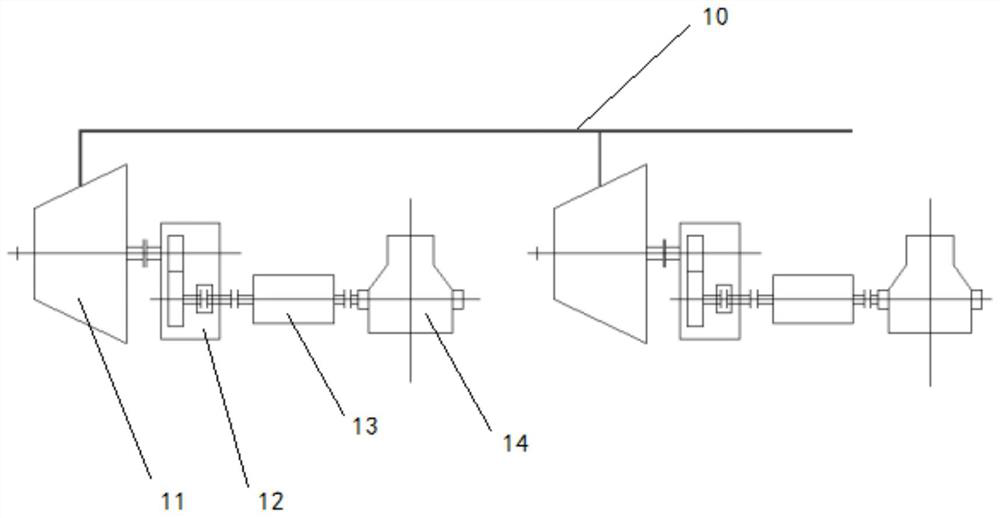
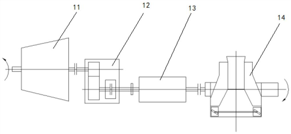
[0028] This embodiment provides a sintering steam drag system, including: a plurality of main exhaust fan structures and a waste heat boiler, the main shaft fan structure includes a steam turbine, a variable speed clutch, a synchronous motor and a sintering main shaft fan connected in sequence, and the steam turbine passes through The variable speed clutch is connected with the main shaft fan, and adopts the overrunning clutch technology to realize the combination and separation of the main exhaust fan; the steam turbine of each main shaft fan structure is connected to the waste heat boiler through the waste heat main steam pipeline;
[0029] When the speed of the low-speed shaft of the variable speed clutch is equal to the speed of the sintered main fan, the variable speed clutch connects the steam turbine and the fan, so that the steam turbine drives the main exhaust fan, and the synchronous motor is adjusted by the excitation system, and the output power gradually decreases t...
Embodiment approach
[0031] As an embodiment, the steam turbine includes a waste heat steam source, a steam turbine high-pressure cylinder, a steam turbine low-pressure cylinder, a surface heat exchanger, a generator, and a condenser or a steam exhaust device. The steam turbine high-pressure cylinder and the steam turbine low-pressure cylinder are connected to the power generation The waste heat steam source is provided by the waste heat boiler through the waste heat main steam pipeline. The waste heat steam source is divided into two paths, one of which is the main steam a is connected to the high pressure cylinder of the steam turbine, and the other main steam b is connected to the surface heat exchanger. The exhaust steam of the high-pressure cylinder of the steam turbine is connected to the surface heat exchanger through a pipeline, and the exhaust steam c of the high-pressure cylinder of the steam turbine and the main steam b conduct heat exchange in the surface heat exchanger. The steam outle...
Embodiment 2
[0040] The present embodiment provides a working method of a sintered steam drag system, including:
[0041] The high temperature steam generated by the waste heat boiler is transported to the steam turbine through the waste heat main steam pipeline and drives the steam turbine;
[0042] After the steam turbine drives the speed change clutch to decelerate, when the speed of the low speed shaft of the speed change clutch is equal to the speed of the sintered main fan, the speed change clutch connects the steam turbine and the fan, so that the steam turbine drives the main exhaust fan;
[0043] The excitation system of the synchronous motor is adjusted, so that the output power is gradually reduced to achieve the purpose of energy saving; at this time, the energy required by the main exhaust fan mainly comes from the steam turbine, and the insufficient part is compensated by the synchronous motor.
[0044] A plurality of main exhaust fan structures and waste heat boilers, the ma...
PUM
 Abstract
Description
Claims
Application Information
 - R&D
- Intellectual Property
- Life Sciences
- Materials
- Tech Scout
- Unparalleled Data Quality
- Higher Quality Content
- 60% Fewer Hallucinations
Browse by: Latest US Patents, China's latest patents, Technical Efficacy Thesaurus, Application Domain, Technology Topic, Popular Technical Reports.
© 2025 PatSnap. All rights reserved.Legal|Privacy policy|Modern Slavery Act Transparency Statement|Sitemap|About US| Contact US: help@patsnap.com


