Fixed combustible gas detection alarm

A fixed, alarm technology, applied in the directions of alarms, instruments, supporting machines, etc., can solve the problem that the alarm cannot be installed and fixed, and achieve the effect of convenient installation and fixing

Active Publication Date: 2022-07-08
深圳市东大智勇工程有限公司
View PDF10 Cites 2 Cited by
  • Summary
  • Abstract
  • Description
  • Claims
  • Application Information

AI Technical Summary

Problems solved by technology

[0006]The present invention can mainly solve the problem that the alarm cannot be quickly installed and fixed according to the installation position

Method used


Image

  • Fixed combustible gas detection alarm
  • Fixed combustible gas detection alarm
  • Fixed combustible gas detection alarm

Examples


Embodiment 1

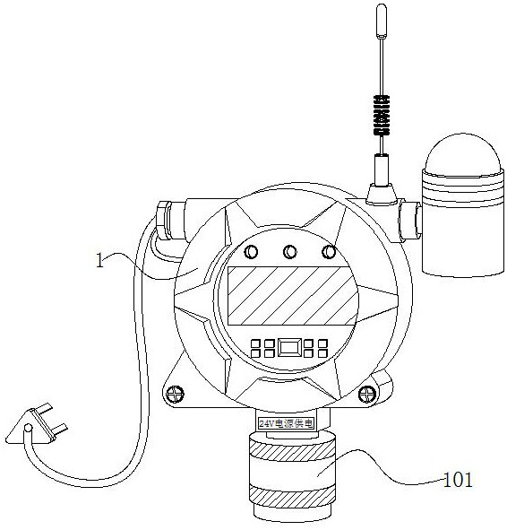
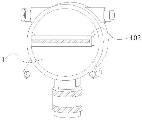
[0036] Embodiment 1: A fixed combustible gas detection alarm, including an alarm device 1, a sensor 101 is installed at the lower end of the alarm device 1, a bracket 102 is installed on the back of the alarm device 1, and the inside of the bracket 102 is provided with a negative pressure Quickly installed transmission mechanism;

[0037] A chip is installed inside the alarm device 1, and an information transmission device is installed inside the alarm device 1. The chip is connected to the receiving end of the cloud platform through the information transmission device. When the sensor 101 detects a combustible gas, the sensor 101 transmits the signal to the chip. Internally, the chip transmits the wireless signal to the receiving end of the cloud platform;

[0038] Once the fire information is detected, a signal transmitter is installed on the receiving end of the chip and the cloud platform. The chip is wirelessly connected to the cloud platform through the signal transmitte...

Embodiment 2

[0041] Example 2: Reference Manual Attached Figure 3-7It can be seen that the difference between Embodiment 2 and Embodiment 1 is that the transmission mechanism includes a slider 2, a shaft arm 201, a disk 202, a support column 203, a rotating disk 3, a convex strip 301, a rotating shaft 302, a swing arm 303, and a rotating bearing. 4 and the swash plate 401, the slider 2 slides on the inner wall of the bracket 102, the shaft arm 201 slides on one side of the slider 2, the disc 202 swings on the upper end of the shaft arm 201, the support column 203 swings on the upper end of the disc 202, and rotates The disk 3 swings on one side of the disk 202 , the protruding strips 301 are distributed on the outer side of the rotating disk 3 , the rotating shaft 302 is hinged to the lower end of the rotating disk 3 , the swing arm 303 swings on the lower end of the rotating shaft 302 , and the rotating bearing 4 is hinged to the lower end of the column 203 . On the outside, the swash pl...

Embodiment 3

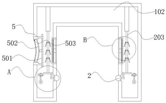
[0050] Example 3: Reference Manual Attached image 3 , 4 , 7 and 8, it can be known that the difference between Embodiment 3 and Embodiments 1 and 2 is that the transmission mechanism includes a fixed frame 5, an extrusion frame 501, an adsorption layer 502, a negative pressure valve 503, a sleeve 6, a folding tube 601, The intake pipe 602 and the limiting frame 603, the fixing frame 5 is embedded on both sides of the bracket 102, the extrusion frame 501 slides on the inner wall of the fixing frame 5, the adsorption layer 502 is elastically stretched on the other side of the inner wall of the fixing frame 5, the negative pressure valve 503 runs through the inner wall of the adsorption layer 502, the sleeve 6 is installed on the other side of the bracket 102, the folding tube 601 is folded and retracted inside the sleeve 6, the air intake pipe 602 runs through one end of the folding tube 601, and the limiter 603 slides on one side of the folded tube 601;

[0051] Among them: ...


PUM


Abstract

The invention provides a fixed combustible gas detection alarm which comprises an alarm device, a sensor is installed at the lower end of the alarm device, a support is installed on the back face of the alarm device, a transmission mechanism capable of forming rapid installation through negative pressure is arranged in the support, the sensor is electrically connected with the alarm device, and the sensor is a gas sensor. When the support penetrates through the back face of the sensor and the shaft arm and moves to the other side of the lower end of the disc, an antenna is installed at the upper end of the alarm device, and the antenna is a transmission device for transmitting and receiving signals and can enhance signals of the information transmission device. Due to the fact that the swing arm is arranged at the lower end of the rotating shaft, and the weight of the swing arm is larger than that of the protruding strip and the rotating disc, the rotating disc rapidly returns after swinging for a short time, the rotating disc can assist the shaft arm in returning through the protruding strip, and meanwhile when one side of the sliding block loses extrusion, the sliding block can be driven by the shaft arm to return.

Description

technical field [0001] The invention relates to the technical field of gas detection equipment, in particular to a fixed combustible gas detection alarm. Background technique [0002] With the continuous development of industrial gas transportation, various hazardous gas alarms have gradually become indispensable protective equipment in industrial safety production. When flammable gas is transported, it needs to be alarmed by detection alarms to avoid flammable gas leakage. Technical implications for alarms; [0003] A study of the alarms found the following problems: [0004] The alarm is usually installed on the inner wall of the gas pipeline or gas detection equipment. When the alarm is installed, it can usually only be installed with bolts. Because the gas pipeline needs to be snap-fitted, and the gas detection equipment needs to be installed on the wall, resulting in The alarm cannot be quickly installed according to the installation method of snap-on or wall-mounted ...

Claims


Application Information

Patent Timeline
Patent Type & Authority Applications(China)
IPC IPC(8): G08B21/16F16M11/04
CPCG08B21/16F16M11/041Y02A50/20
Inventor 胡卫锋
Owner 深圳市东大智勇工程有限公司
Why Eureka
Try Eureka