Eureka AIR delivers breakthrough ideas for toughest innovation challenges, trusted by R&D personnel around the world.

Resistance spot welding butt joint process

A technology of resistance spot welding and process, applied in the direction of resistance welding equipment, welding equipment, welding/welding/cutting items, etc., can solve problems such as joint quality decline, nugget offset, nugget size small, etc., to solve the nugget Effects of small size, increased nugget size, and improved quality

Pending Publication Date: 2022-07-12
TIANJIN UNIV
View PDF5 Cites 0 Cited by
  • Summary
  • Abstract
  • Description
  • Claims
  • Application Information

AI Technical Summary

Problems solved by technology

[0003] At present, most of the resistance spot welding technology is welded in the form of lap joints, but there are still shortcomings in the use of lap joints to connect plates: on the one hand, the equipment and technical requirements for lap spot welding of thicker plates are relatively high , and the size of the nugget formed when the thicker plates are overlapped is smaller; on the other hand, in the field of industrial production, there is a high demand for welded joints of dissimilar plates (aluminum alloy and stainless steel, titanium alloy and stainless steel, etc.)
When lap joints are used, due to the huge difference in heat treatment properties (resistivity, thermal conductivity) between dissimilar materials, it is easy to produce a hard and brittle intermetallic compound layer, resulting in the offset of the nugget, which significantly reduces the quality of the joint. It hinders the application of resistance welding technology in industrial production

Method used


Image

  • Resistance spot welding butt joint process
  • Resistance spot welding butt joint process
  • Resistance spot welding butt joint process

Examples


Embodiment 1

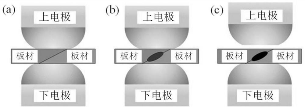
[0049] refer to figure 1 , a resistance spot welding butt welding process, comprising the following steps:

[0050] (1) Contact the upper electrode with the first workpiece to be welded;

[0051] (2) contacting the lower electrode with the second workpiece to be welded;

[0052] (3) Abutting the first workpiece to be welded and the second workpiece to be welded, the first butt surface of the first workpiece to be welded and the second butt surface of the second workpiece to be welded are in direct contact (see figure 1 in (a));

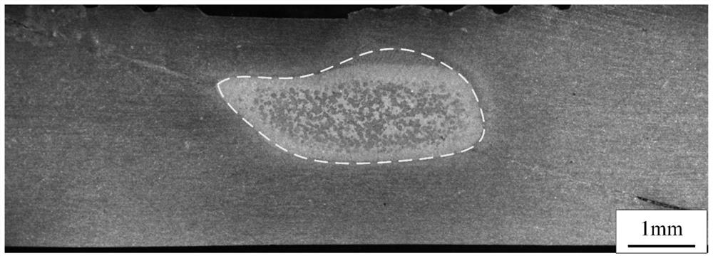
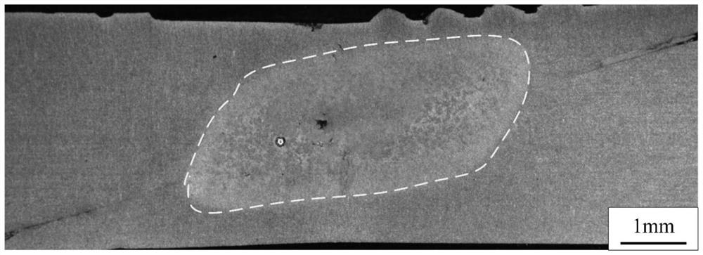
[0053] (4) Apply pressure and welding current to the upper electrode and the lower electrode to perform resistance spot welding, and the size of the nugget gradually changes during the spot welding process, see figure 1 in (b) and (c).

[0054] Wherein, the first workpiece to be welded and the second workpiece to be welded are both 4mm 5754 aluminum alloy; the upper electrode and the lower electrode are electrodes made of CuCrZr material.

[0...

Embodiment 2

[0058] A resistance spot welding butt welding process, comprising the following steps:

[0059] (1) Contact the upper electrode with the first workpiece to be welded;

[0060] (2) contacting the lower electrode with the second workpiece to be welded;

[0061] (3) butting the first workpiece to be welded and the second workpiece to be welded, the first butt surface of the first workpiece to be welded and the second butt surface of the second workpiece to be welded are in direct contact;

[0062] (4) Resistance spot welding is performed by applying pressure and welding current to the upper electrode and the lower electrode.

[0063] Wherein, the first workpiece to be welded and the second workpiece to be welded are both 4mm 5754 aluminum alloy; the upper electrode and the lower electrode are electrodes made of CuCrZr material.

[0064] Wherein, the first abutting surface and the second abutting surface are inclined surfaces that cooperate with each other, and the slope angle o...

Embodiment 3

[0067] A resistance spot welding butt welding process, comprising the following steps:

[0068] (1) Contact the upper electrode with the first workpiece to be welded;

[0069] (2) contacting the lower electrode with the second workpiece to be welded;

[0070] (3) butting the first workpiece to be welded and the second workpiece to be welded, the first butt surface of the first workpiece to be welded and the second butt surface of the second workpiece to be welded are in direct contact;

[0071] (4) Resistance spot welding is performed by applying pressure and welding current to the upper electrode and the lower electrode.

[0072] Wherein, the first workpiece to be welded and the second workpiece to be welded are both 4mm 5754 aluminum alloy; the upper electrode and the lower electrode are electrodes made of CuCrZr material.

[0073] Wherein, the first abutting surface and the second abutting surface are inclined surfaces that cooperate with each other, and the slope angle o...


PUM

PropertyMeasurementUnit
thicknessaaaaaaaaaa
thicknessaaaaaaaaaa

Abstract

The invention provides a resistance spot welding butt joint process. The resistance spot welding butt joint process comprises the steps that an upper electrode makes contact with a first to-be-welded workpiece; the lower electrode makes contact with a second workpiece to be welded; the first to-be-welded workpiece and the second to-be-welded workpiece are in butt joint; and pressure and welding current are applied to the upper electrode and the lower electrode for resistance spot welding. According to the resistance spot welding butt joint technology, on the basis that new equipment does not need to be introduced, the first to-be-welded workpiece and the second to-be-welded workpiece are connected in a butt joint mode, welding between thick plate materials is achieved, the nugget size is increased, and the problem that the nugget size is small is solved; and meanwhile, welding of dissimilar materials can be achieved, the quality of a welded joint is improved, the structure is simple, and limitation of the size of a workpiece can be avoided.

Description

technical field [0001] The present application relates to the technical field of resistance spot welding, and in particular, to a butt welding process of resistance spot welding. Background technique [0002] Resistance spot welding is to use the contact resistance between the contact surfaces of the workpieces to generate Joule heat to melt the metal and cool and solidify to form a joint through pressure between electrodes and instantaneous energization. Resistance spot welding technology is widely used in practical production due to its advantages of easy automation, high efficiency, low pollution and low cost. Resistance spot welding is widely used in traditional manufacturing, especially in the automotive industry, where resistance spot welding accounts for nearly 60% of the workload in the manufacturing process. Resistance spot welding is generally used for the connection of magnesium alloys, aluminum alloys, titanium alloys, steel, etc. [0003] At present, most of t...

Claims


Application Information

Patent Timeline
Patent Type & Authority Applications(China)
IPC IPC(8): B23K11/11B23K33/00B23K103/10B23K103/20B23K103/24
CPCB23K11/115B23K33/00B23K2103/10B23K2103/20B23K2103/24
Inventor 罗震杨越毕元波郭璟张熠轩苏杰
Owner TIANJIN UNIV
Why Eureka
Eureka Blog
Learn More