Environment-friendly cooling device for energy storage power station

A technology of cooling device and energy storage power station, which is applied in the direction of substation/distribution device casing, substation/switchgear cooling/ventilation, energy storage, etc. , to achieve the effect of improving the heat dissipation effect, improving the cleaning effect and improving the cooling effect

Pending Publication Date: 2022-07-12
海宁市金能电力实业有限公司
View PDF2 Cites 0 Cited by
  • Summary
  • Abstract
  • Description
  • Claims
  • Application Information

AI Technical Summary

Problems solved by technology

[0005] There are also certain problems in the content disclosed in the above patent: (1) The air-cooled heat dissipation mode is adopted. During the internal heat dissipation process, the external wind is blown into the interior of the power station for heat dissipation. Over time, the surface of the heat dissipation structure is easy to accumulate A large amount of dust greatly reduces the heat dissipation effect, and the air-cooled heat dissipation effect is not good, and the internal temperature of the power station cannot be effectively treated; (2) The water circulation heat dissipation mode cannot make rational use of natural resources, resulting in waste of resources, which does not conform to the concept of environmental protection

Method used


Image

  • Environment-friendly cooling device for energy storage power station
  • Environment-friendly cooling device for energy storage power station
  • Environment-friendly cooling device for energy storage power station

Examples


Embodiment Construction

[0040] The following are specific embodiments of the present invention and the accompanying drawings to further describe the technical solutions of the present invention, but the present invention is not limited to these embodiments.

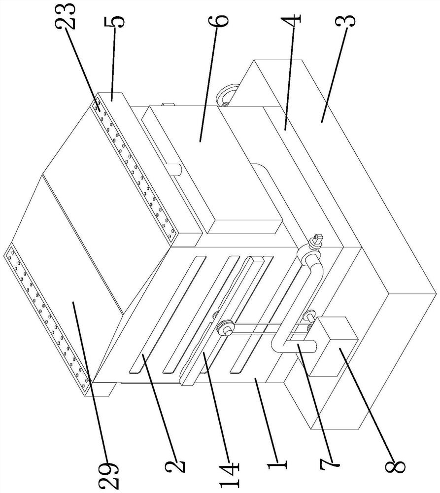
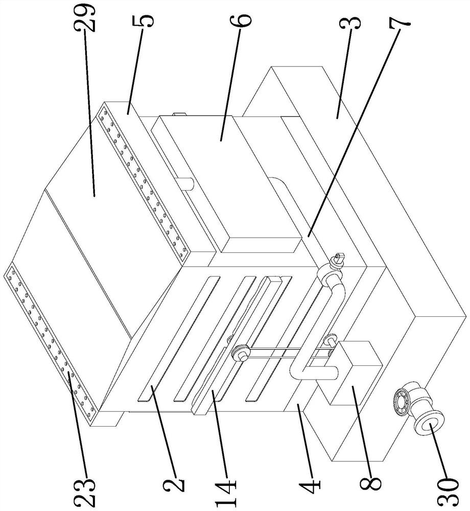
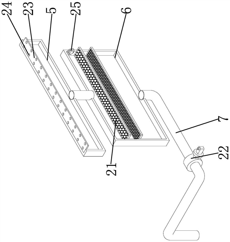
[0041] like Figure 1-Figure 7As shown in the figure, the environmental protection cooling device used in the energy storage power station includes a power station body 1. The left and right sides of the surface of the power station body 1 are provided with heat dissipation grooves 2, and a dust-proof net is installed inside the heat dissipation groove 2. The bottom of the power station body 1 A bottom plate 4 is fixed, a base 3 is fixed below the bottom plate 4, a collection cover 5 is bolted on the top of the front and rear sides of the power station body 1, and an incubator 6 is fixed on the front and rear sides of the power station body 1 and below the collection cover 5, And the insulation box 6 is communicated with the collection cover 5, ...


PUM


Abstract

The invention provides an environment-friendly cooling device for an energy storage power station, belongs to the technical field of energy storage power stations, and solves the problem that an existing cooling device cannot collect and utilize rainwater and causes resource waste. The environment-friendly cooling device for the energy storage power station comprises a power station body, heat dissipation grooves are formed in the left side and the right side of the surface of the power station body, dustproof nets are installed in the heat dissipation grooves, a bottom plate is fixed to the bottom of the power station body, and a base is fixed to the lower portion of the bottom plate. Through the arrangement of the collecting cover, the heat preservation box, the water passing pipe, the water tank, the water pump and the water cooling pipe, the device can collect and reasonably utilize outside rainwater, water cooling treatment is conducted on the power station through the rainwater, the cooling effect is improved, and through the arrangement of the water wheel, the driving wheel, the driven wheel, the rotating plate and the cleaning brush, the cleaning effect is improved. And the device can automatically clean dust on the surface of the heat dissipation structure, and the heat dissipation effect is further improved.

Description

technical field [0001] The invention belongs to the technical field of energy storage power stations, and relates to a cooling device, in particular to an environment-friendly cooling device for energy storage power stations. Background technique [0002] Energy storage power station: an equipment system for the storage, conversion and release of recyclable electrical energy through electrochemical cells or electromagnetic energy storage media; the main storage means are mostly pumped energy storage power stations and ultra-large battery packs, the purpose is to adjust the peak and valley power consumption problems . [0003] After searching, for example, Chinese patent documents disclose a battery energy storage power station with a real-time monitoring safety device [application number: CN202022318580.2; publication number: CN213213188U]. The battery energy storage power station with real-time monitoring safety device includes an energy storage box, a handle, a door and a...

Claims


Application Information

Patent Timeline
IPC IPC(8): H02B1/56H02B1/28B08B1/04B08B1/00B01D46/681B01D46/42B01D46/10
CPCH02B1/565H02B1/28B01D46/10B01D46/4227B08B1/12B08B1/32Y02E70/30
Inventor 陈铭雷象兵叶翔胡明达徐杰朱超峰顾卿张艰
Owner 海宁市金能电力实业有限公司
Why Eureka
Try Eureka