Radio frequency front-end assembly adopting high-performance ceramic material

A technology of radio frequency front-end and radio frequency components, which is applied in the field of communication, can solve problems such as poor performance, low efficiency, and high production cost, and achieve the effects of simple structure, saving transmission power, and small size

Pending Publication Date: 2022-07-12
南京瑞基通讯技术有限公司
View PDF1 Cites 0 Cited by
  • Summary
  • Abstract
  • Description
  • Claims
  • Application Information

AI Technical Summary

Problems solved by technology

[0005] The purpose of the present invention is to provide a new type of radio frequency front-end component for the problems of poor performance, low efficiency and high production cost caused by unreasonable design and material application limitations of the existing radio frequency front-end components, which can be used in wireless communication As a wireless RF...

Method used


Image

  • Radio frequency front-end assembly adopting high-performance ceramic material
  • Radio frequency front-end assembly adopting high-performance ceramic material
  • Radio frequency front-end assembly adopting high-performance ceramic material

Examples


Embodiment 1

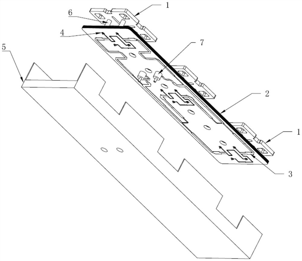
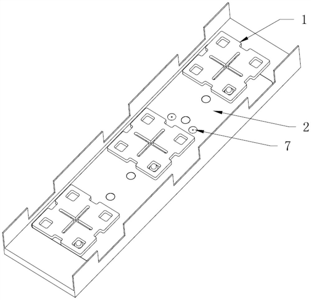
[0042] figure 1 and figure 2 It is a radio frequency front-end assembly composed of a single unit, including three metal radiating units 1, a core power division network substrate 2 and a mounting frame 5; the core power division network substrate 2 is fired from microwave dielectric ceramic materials. A dielectric ceramic substrate with a power division network and a shielding cover, a through hole 4 is provided on the core power division network substrate 2 for installing the pins 6 and signal terminals 7 of the metal radiating unit 1, and on the front side of the core power division network substrate 2 A non-metallic ring layer is provided around the through holes used to install the pins 6 and the signal terminals 7, and the width of the non-metallic ring layer is 1-10 mm; on the front side of the core power division network substrate 2, unless the metal ring layer is peripheral There is a metal layer; the four sides of the core power division network substrate 2 are met...

Embodiment 2

[0051] A protective cover made of an organic polymer is placed on a single RF front-end component in Example 1 to meet the needs of an all-weather working environment in a natural environment.

Embodiment 3

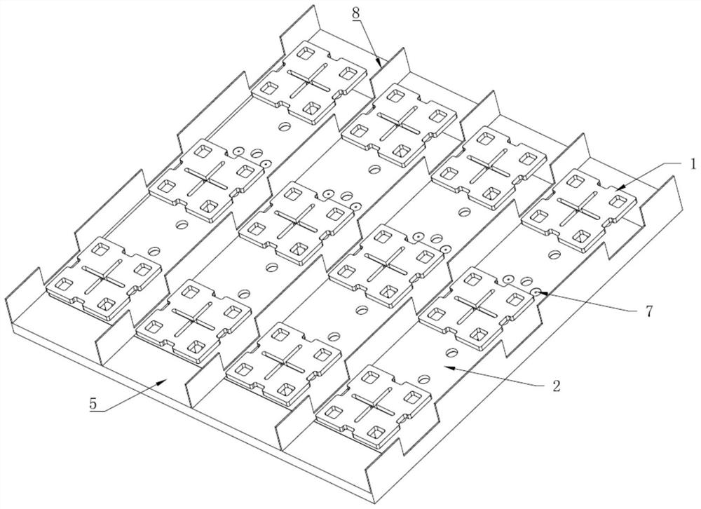
[0053] like image 3 As shown, on the basis of Embodiment 1, the number of the mounting frame 5 and the core power division network substrate 2 in the radio frequency front-end assembly is adjusted to obtain a radio frequency front-end assembly composed of four units.

[0054] The RF front-end assembly in this embodiment is composed of four installation frames 5, and spacers 8 are arranged between adjacent installation frames 5; a core power division network substrate 2 is installed in each installation frame 5, and each core power division network The substrate 2 is mounted with 3 pieces of metal radiation units 1 and 2 pieces of PIN pins as signal lead-out terminals 7 to form a four-unit mode.

[0055] The total size of the RF front-end component in this embodiment is 175mm×150mm×24mm, which is a high-performance RF front-end component that can be implemented within 3.3-3.75GHz, SWR22dB, and gain: 11.0-13.5dB.


PUM


Abstract

The invention discloses a radio frequency front-end assembly, which comprises a radio frequency assembly, the radio frequency assembly comprises at least one mounting frame with a groove, and each mounting frame is internally provided with at least one core power division network substrate; at least one radiation unit is arranged on the front surface of the core power division network substrate, a circuit is arranged on the back surface of the core power division network substrate, and at least one through hole is formed in the core power division network substrate; the pins of the radiation unit pass through the through holes of the core power division network substrate and are connected with the circuit on the back surface of the core power division network substrate. And a signal leading-out end is arranged in the through hole of the core power division network substrate, and the signal leading-out end passes through the mounting frame to transmit a signal to the signal processing unit at the rear section. According to the radio frequency front-end assembly, the interference of external signals on a system is greatly reduced while the transmission loss is greatly reduced, so that the working efficiency of the assembly is greatly improved, and the radio frequency front-end assembly plays a significant role in improving the sensitivity of the system and saving the energy consumption of the whole system.

Description

technical field [0001] The invention belongs to the technical field of communications, and relates to a radio frequency front-end assembly, in particular to a radio frequency front-end assembly using high-performance ceramic materials. Background technique [0002] At the end of the nineteenth century, mankind opened the door to wireless communication. Since then, wireless communication technology has profoundly changed human society and greatly promoted the development of modern human civilization. With the popularization and continuous development of wireless communication technology, the modern social space is full of radio wave signals of various frequency bands, and the performance requirements for various civil and military wireless communication equipment are getting higher and higher. The ability to pick up weak signals and ensure stable communication under various interference conditions has become the primary condition for measuring the performance of modern commun...

Claims


Application Information

Patent Timeline
IPC IPC(8): H04B1/40C04B35/453
CPCH04B1/40C04B35/453C04B2235/3217C04B2235/3232C04B2235/3227C04B2235/3201C04B2235/3272C04B2235/3418C04B2235/3251C04B2235/3244C04B2235/3289C04B2235/3224C04B2235/3267C04B2235/3281C04B2235/96Y02D30/70H05K7/1422H05K1/0306H05K1/18H01Q1/368
Inventor 薛冰陈兵红高杪
Owner 南京瑞基通讯技术有限公司
Why Eureka
Try Eureka