Intelligent electric cabinet dehumidification device

An electric cabinet and intelligent technology, applied in substation/distribution device shell, separation method, separation of dispersed particles, etc., can solve problems such as secondary terminal breakdown, corrosion of steel structural parts, and mildew of materials

Active Publication Date: 2022-07-15
江苏英美迪自动化科技有限公司
View PDF8 Cites 0 Cited by
  • Summary
  • Abstract
  • Description
  • Claims
  • Application Information

AI Technical Summary

Problems solved by technology

[0002] The power distribution cabinet is an important power equipment in the power supply system of the community or the current transmission of the electric tower, and an important reason that affects the normal operation of the power equipment is the ambient temperature and humidity. Potential safety hazards such as aging, reduction of dielectric strength, breakdown of secondary terminals, mildew of materials, and corrosion of steel structural parts
[0003] At present, due to the continuous increase of the single unit capacity of the current power system, the continuous expansion of the grid capacity, the continuous increase of the transmission voltage, and the continuous increase of the transmission distance and transmission capacity, the load on the electric meter and the wire will be too large, coupled with environmental changes. The problem of humidity in the distribution cabinet can easily cause a series of electrical disasters such as short circuit and burning of the wires on the meter.

Method used


Image

  • Intelligent electric cabinet dehumidification device
  • Intelligent electric cabinet dehumidification device
  • Intelligent electric cabinet dehumidification device

Examples


Embodiment 1

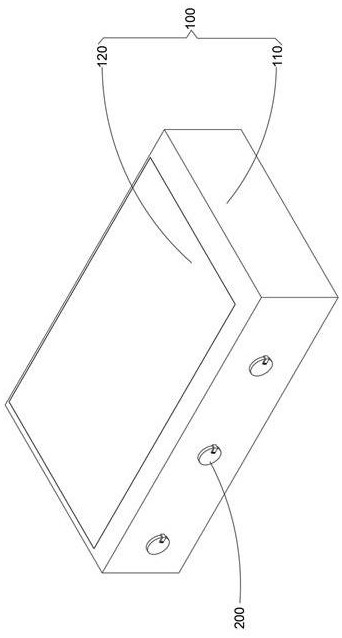
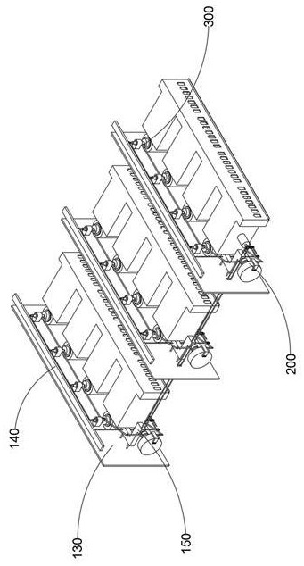
[0047] combine Figure 1-9 As shown, the intelligent electrical cabinet dehumidification device provided by the present invention includes a sealing mechanism 100, an airflow replacement mechanism 200, an airflow transmission mechanism 300, and an air bleed pipeline 400. The airflow replacement mechanism 200 is installed in the sealing mechanism 100, and the airflow transmission mechanism 300 is connected Inside the sealing mechanism 100 , and drivingly connected to the airflow displacement mechanism 200 , in addition, the air bleed pipeline 400 is connected to the airflow displacement mechanism 200 and the airflow transmission mechanism 300 .

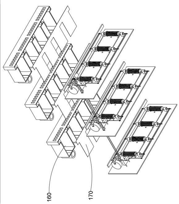
[0048] The sealing mechanism 100 includes a hood 110, a sealing cover 120, a baffle 130, a backing plate 140, an auxiliary clamping slot 150, an electric meter cover 160 and a plug-in plate 170, and the airflow displacement mechanism 200 includes a motor 210, an air chamber shaft 220, a shaft 230, The transmission rod 240 , the ring bu...

Embodiment 2

[0051] combine Figure 5 and 6 As shown, on the basis of the first embodiment, the inwardly recessed chute is provided on the inner side of the two trapezoidal housings, so as to facilitate the safe rotation of the air chamber shaft 220 as a whole, and combined with its outer middle air pipe to penetrate to the moisture absorbing member The inner cavity of 290 extends to the inner third of the cavity, so that the dried air flow can be stably conveyed, and at the same time, combined with the absorption of heat energy by the turning element 270 itself, when the turning element 270 absorbs the anhydrous carbonic acid During the stirring of calcium, the external heat energy of the turning element 270 can heat and evaporate the anhydrous calcium carbonate powder, and use a larger cavity to store the turning element 270 and the anhydrous calcium carbonate powder, so that the processing can be improved. The rear air is discharged in an orderly manner. The cabin body 222 is composed ...

Embodiment 3

[0053] combine figure 1 , 2 , 3, 7 and 8, in the above embodiment, the turbine rods 330 symmetrically distributed in the vertical direction are arranged along the top and bottom holes of the mesh cylinder 361, and the transmission rod 240 is opposite to the two Under the driving action of the vertical shaft 310 , the two turbine rods 330 will form a directional airflow inside the mesh cylinder 361 , and combined with the meter ventilation element 360 as a whole, the secondary filter layer is realized by splicing, so that the airflow in the inner cavity of the meter cover 160 can be achieved. The moisture carried in the air is adsorbed, the turbine rod 330 is composed of a vertical rod, a fan blade and a gear, and the fan blade is adapted to be installed in the cylindrical air hood opened on the load-bearing member 340, and the mesh cylinder 361 is made of stainless steel. The mesh cylinder 361 is provided with evenly distributed fan-shaped slot holes, and two sides of the fan...


PUM


Abstract

The invention discloses an intelligent electric cabinet dehumidification device, which comprises a sealing mechanism, an airflow replacement mechanism, an airflow transmission mechanism and an air entraining pipeline, and is characterized in that the sealing mechanism comprises a partition plate, a base plate and an auxiliary clamping groove connected to the partition plate, a moisture absorption piece capable of loading anhydrous calcium carbonate powder is installed on a machine cover, a ring piece for isolating the calcium carbonate powder is installed in an inner cavity of the moisture absorption piece, a turnover piece erected in a suspended mode is arranged in the inner cavity of the moisture absorption piece, and meanwhile a gas cabin shaft is combined to convey hot gas in the power distribution cabinet to the inner cavity of the moisture absorption piece as a whole. An air inlet piece and a guide pipe on the buckle are used for communicating a cavity, far away from calcium carbonate, in the moisture absorption piece with the ring piece, so that air in an external environment can pass through calcium carbonate powder when entering the air cabin shaft through the moisture absorption piece; therefore, the device can ventilate the inner cavity of the power distribution cabinet, and can ensure that the interior of the power distribution cabinet is not subjected to condensation caused by temperature difference change at the same time.

Description

technical field [0001] The invention relates to the technical field of electrical cabinet dehumidification, in particular to an intelligent electrical cabinet dehumidification device. Background technique [0002] When the power distribution cabinet is an important power equipment in the power supply system of the community or the current transmission of the tower, an important reason that affects the normal operation of the power equipment is the ambient temperature and humidity. Aging, reduced insulation strength, secondary terminal breakdown, material mildew and corrosion of steel structure and other safety hazards. [0003] At present, due to the continuous increase of the single unit capacity of the current power system, the continuous expansion of the power grid capacity, the continuous increase of the transmission voltage, the continuous increase of the transmission distance and the transmission capacity, it will lead to the excessive load of the electric meter wire, ...

Claims


Application Information

Patent Timeline
Patent Type & Authority Applications(China)
IPC IPC(8): B01D53/28B01D53/26H02B1/28
CPCB01D53/28B01D53/261H02B1/28B01D2257/80B01D2253/10Y02A30/14
Inventor 田荣华陈万才
Owner 江苏英美迪自动化科技有限公司
Why Eureka
Try Eureka