Numerical control machine tool

A numerically controlled machine tool, debris technology, applied to metal processing machinery parts, separation methods, filtration and separation, etc., can solve the problems that debris cannot be cleaned by brushes, debris cannot be blown away, etc. Achieve the effect of improving convenience, improving protection effect and preventing splash

Pending Publication Date: 2022-07-15
李振民
View PDF1 Cites 0 Cited by
  • Summary
  • Abstract
  • Description
  • Claims
  • Application Information

AI Technical Summary

Problems solved by technology

[0004] Yet above-mentioned prior art has the following technical defect: when machine tool is working, above-mentioned device carries out air blowing cleaning to machine tool body interior on a large scale, debris is blown up by gas at first, so that machine tool interior and above-mentioned device that are installed in machine tool interior will be Attached part of the debris, although the internal side wall of the machine tool will be cleaned by the brush, but some debris attached to the small gap cannot be cleaned by the brush, and the brush only cleans the internal side wall of the machine tool, and cannot clean the above-mentioned device Although most of the debris will be blown away by the gas, the debris falling in the gaps of the above-mentioned devices cannot be blown away or cleaned by a brush. Over time, if there are too many debris stored in the gaps, manual cleaning is required. clean it up

Method used


Image

  • Numerical control machine tool
  • Numerical control machine tool
  • Numerical control machine tool

Examples


Embodiment 1

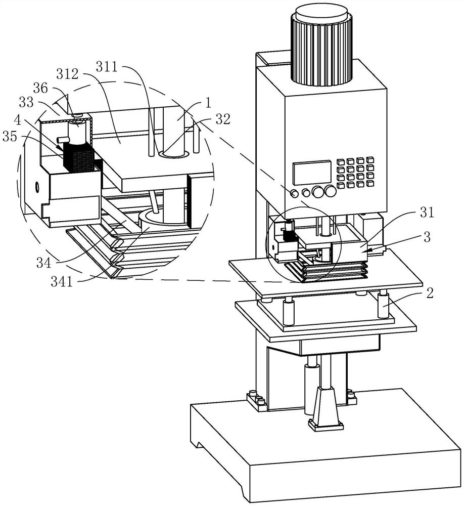
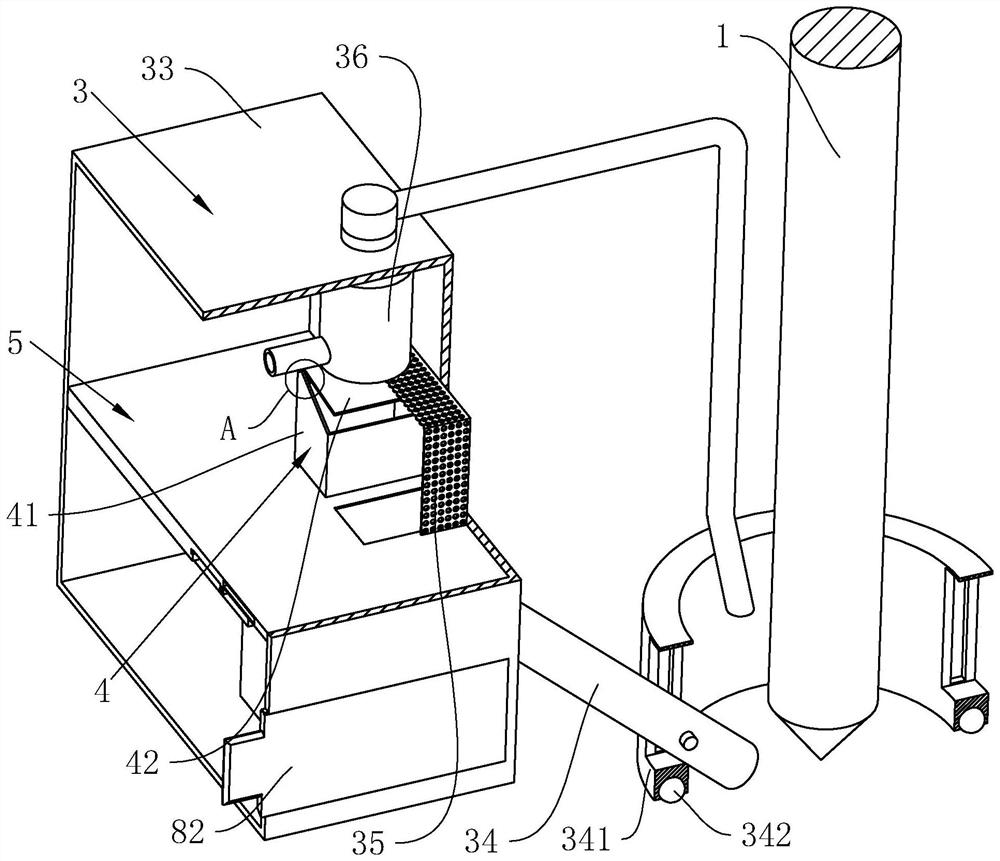
[0043] refer to figure 1 As shown, in order to recover the debris generated by the drill bit 1 and to synchronously cool the drill bit 1, in this embodiment, a debris cleaning device 3 is arranged between the telescopic seat and the support plate in the processing area; The debris cleaning device 3 includes a debris cover 31, a fixed bearing 32, a device box 33, a suction pipe 34, a filter cover 35, a high-pressure water pump 36 and a circulating storage device 4; Cover installation, the chip cover 31 is provided with a mounting groove 311 for the drill bit 1 to be installed through, and the bottom of the chip cover 31 is in conflict with the top of the plate to be cut, and the lower half of the chip cover 31 is set as a retractable material cover The fixed bearing 32 is arranged between the outer side wall of the drill bit 1 and the side wall of the installation groove 311 to install the debris cover 31, and the outer side wall of the fixed bearing 32 is fixedly arranged on t...

Embodiment 2

[0051] refer to Figure 4 As shown, on the basis of the first embodiment, in order to further reduce the labor of the operator and enable the device to realize automatic operation, the corresponding automatic switch mechanism 6 is installed in the control area in the device box 33, and the automatic switch mechanism 6 includes The delivery pipe 61, the drive rod 62, the limit rod 63, the thrust spring 64 and the water pump switch 65; Therefore, when one end of the suction port of the suction pipe 34 slides in the direction of the drill bit 1 against the plate to be cut, the connecting end of the suction pipe 34 and the conveying pipe 61 moves downward at the same time, that is, the conveying pipe 61 is synchronously driven to move downward; the blocking plate 5 There is a sliding groove 51 for sliding installation of the conveying pipe 61 . It should be noted that the conveying pipe 61 will only move in the sliding groove 51 and will not be separated from the blocking plate 5 ...

Embodiment 3

[0056] refer to Figure 4 , Figure 5 As shown, on the basis of Embodiment 1 and Embodiment 2, in order to ensure that the device can realize automatic debris cleaning and collection, the third embodiment is provided with the relevant technology of debris cleaning and collection, the specific structure is as follows :

[0057] An impurity collection mechanism 7 is installed in the blocking plate 5, and the impurity collection mechanism 7 includes a receiving cylinder 71, a transmission column 72, a transmission bar 73, a first guide block 74, a first diamond block 75, a connecting rod 76 and an isolation plate 77; The material cylinder 71 is fixed on the lower side of the blocking plate 5, and the blocking plate 5 is provided with a through-hole 53 which connects the liquid supply area with the inner cavity of the receiving cylinder 71. The through-hole 53 is located in the covering area of ​​the filter cover 35. When the discharge box 41 discharges debris and cooling liquid...


PUM


Abstract

The invention relates to the technical field of machine tool equipment, in particular to a numerical control machine tool which comprises a numerical control area located on the upper portion of the numerical control machine tool, a machining area located below the numerical control area and a base located below the machining area. A bearing plate and a plurality of bearing columns mounted on the bearing plate are mounted at the bottom of the machining area, a to-be-cut machining plate is borne by the upper portions of the bearing columns, and a scrap cleaning device is arranged between the telescopic base in the machining area and the bearing plate. The numerical control machine tool has the effects that chippings generated during machining of the numerical control machine tool are prevented from splashing and scattering all around, the chippings are collected and treated, and cooling liquid is recycled.

Description

technical field [0001] The present application relates to the technical field of machine tool equipment, in particular to a numerically controlled machine tool. Background technique [0002] CNC machine tool is the abbreviation of digital control machine tool, which is an automatic machine tool equipped with a program control system. The control system can logically process the program specified by the control code or other symbolic instructions, decode it, represent it with coded numbers, and input it into the numerical control device through the information carrier. After arithmetic processing, various control signals are sent by the numerical control device to control the action of the machine tool, and the parts are automatically processed according to the shape and size required by the drawing. During the working process of the CNC machine tool, the tool needs to rotate on the processed product to have the effect of processing it. At the same time, during the processin...

Claims


Application Information

Patent Timeline
Patent Type & Authority Applications(China)
IPC IPC(8): B23Q11/00B23Q11/08B23Q11/10B01D29/11
CPCB23Q11/0046B23Q11/08B23Q11/10B01D29/117
Inventor 李振民
Owner 李振民
Why Eureka
Try Eureka