Low-energy-consumption tube bundle drying machine and using method thereof

A tube bundle drying, low energy consumption technology, applied in dryers, drying chambers/containers, drying solid materials, etc., can solve problems such as thermal denaturation, quality degradation, air pollution, etc., to avoid thermal denaturation, improve energy utilization, The effect of reducing power consumption

Active Publication Date: 2022-07-15
江苏格兰特干燥浓缩设备有限公司
View PDF28 Cites 1 Cited by
  • Summary
  • Abstract
  • Description
  • Claims
  • Application Information

AI Technical Summary

Problems solved by technology

[0005] First, the energy consumption is high, because the heat source used by the device in the above-mentioned reference document is high-temperature raw steam, which inevitably requires more energy; in addition, in the process of drying the material, it is mainly equipped with heat conduction way, while the utilization rate of heat radiation is relatively low
[0006] Second, the drying effect is not good, because the device in the above-mentioned reference document dries the wet material under normal pressure, which makes the dried material often scorched due to excessive temperature, which leads to the drying of the dried material. Quality degradation (that is, thermal denaturation of some materials, especially concentrated protein with high moisture content); in addition, the waste steam generated by drying wet materials contains burnt odor and total impurity particles. If it is directly discharged into the atmosphere, will cause air pollution

Method used


Image

  • Low-energy-consumption tube bundle drying machine and using method thereof
  • Low-energy-consumption tube bundle drying machine and using method thereof
  • Low-energy-consumption tube bundle drying machine and using method thereof

Examples


Embodiment Construction

[0062] In order to more clearly understand the above objects, features and advantages of the present invention, the present invention will be further described below with reference to the accompanying drawings and embodiments. It should be noted that the embodiments of the present application and the features in the embodiments may be combined with each other in the case of no conflict.

[0063] Many specific details are set forth in the following description to facilitate a full understanding of the present invention, however, the present invention may also be implemented in other ways than described herein, and therefore, the present invention is not limited to the specific embodiments of the following disclosure. limit.

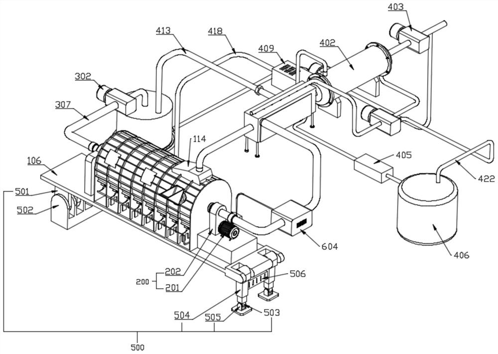
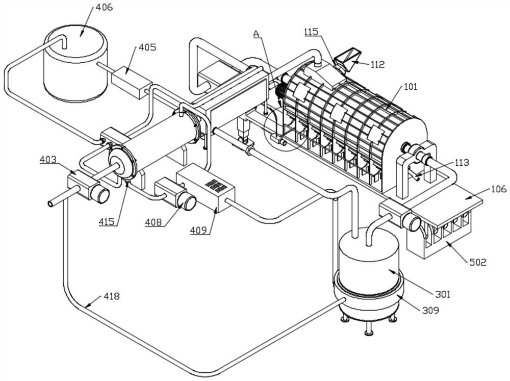
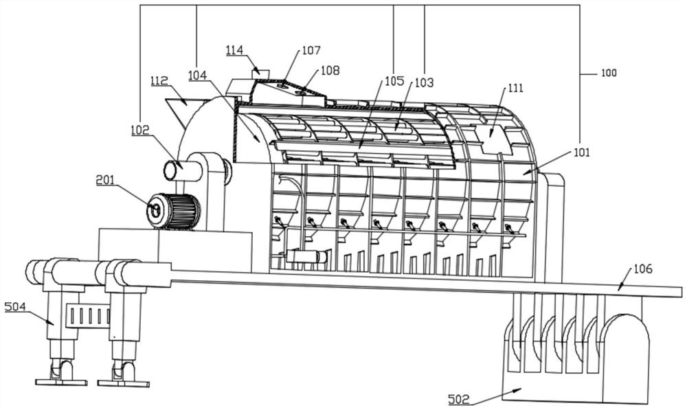
[0064] A low energy consumption tube bundle dryer of this embodiment, refer to Figure 1-9 : including the tube bundle dryer 100 , the swing assembly 500 , the drive assembly 200 , the thermal power assembly 300 , and the recovery assembly 400 .

(one) ...


PUM


Abstract

The invention relates to the technical field of grain machinery, in particular to a low-energy-consumption tube bundle drying machine and a using method thereof. The device comprises a tube bundle drying machine, a swing assembly, a driving assembly, a thermal power assembly and a recovery assembly, the tube bundle drying machine comprises a horizontal housing, a hollow rotating shaft, a drying tube, a hollow disc and a scraper, the horizontal housing is fixedly installed on a bottom plate, and a cylindrical drying cavity is formed in the horizontal housing; the two ends of the horizontal cover shell are both coaxially and rotationally connected with hollow rotating shafts in a dynamic sealing mode, the ends, located in the drying cavity, of the hollow rotating shafts are both coaxially provided with hollow discs, the two hollow discs are connected through a set of evenly-distributed drying pipes, and the outer side walls of the two hollow discs are further connected through a set of evenly-distributed scraping plates; the problems of high energy consumption, poor drying effect and the like in the prior art can be effectively solved.

Description

technical field [0001] The invention relates to the technical field of grain machinery, in particular to a low-energy consumption tube bundle dryer and a method for using the same. Background technique [0002] The tube bundle dryer includes a horizontal cylindrical casing. The casing is surrounded by upper and lower halves. The tube bundle rotor is installed in the inner cavity of the casing. The two ends of the tube bundle rotor are respectively provided with heads, and the center of the head is respectively provided with a rotor shaft. , the rotor shaft drives the tube bundle rotor to rotate under the drive of the driving device, the material is added into the machine body from one end of the casing, falls on the rotating tube bundle, and is indirectly heated by the heat medium in the tube bundle, and then the material is removed by hot air convection. After the air is saturated with water vapor, it is discharged from the exhaust port at the top of the casing and drawn aw...

Claims


Application Information

Patent Timeline
Patent Type & Authority Applications(China)
IPC IPC(8): F26B17/20F26B23/10F26B21/00F26B21/08F26B25/04F26B25/00F26B25/10F25B29/00F25B21/02
CPCF26B17/20F26B23/10F26B21/002F26B21/08F26B25/04F26B25/007F26B25/005F25B29/00F25B21/02F26B25/10F26B21/004Y02P70/10
Inventor 刘亚明彭锋张文利
Owner 江苏格兰特干燥浓缩设备有限公司
Why Eureka
Try Eureka