Fuel cell heat exchanger utilizing liquid hydrogen, fuel cell system and vehicle
A fuel cell system and fuel cell technology, applied in the direction of fuel cell heat exchange, fuel cells, fuel cell additives, etc., can solve the problems of large intercooler, large power consumption, and insufficient utilization of energy ladders, etc., to reduce Radiator, reduce power consumption, improve the effect of energy utilization
- Summary
- Abstract
- Description
- Claims
- Application Information
AI Technical Summary
Problems solved by technology
Method used
Image
Examples
Embodiment 1
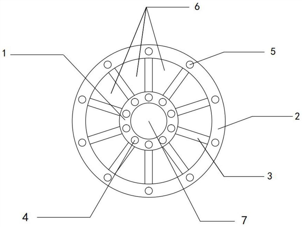
[0035] This embodiment provides a fuel cell heat exchanger using liquid hydrogen, refer to figure 1 As shown, the fuel cell heat exchanger is provided with an inner ring 1 and an outer ring 2, the inner ring 1 and the outer ring 2 communicate with each other through a number of fins 3, and the inner ring 1 is provided with a hydrogen inlet 4, so The outer ring 2 is provided with a hydrogen outlet 5 , an air flow cavity is formed between the plurality of fins 3 and the housing of the fuel cell heat exchanger, and the air flow cavity includes an air inlet 6 and an air outlet 7 .
[0036] In this embodiment, a number of fins can be arranged in a spoke-like arrangement, and a number of fins can be arranged in a large number. The more fins, the better the heat exchange effect. The fins conduct heat exchange to cool the air; low-temperature hydrogen flows in the fins, and the hydrogen inlet can be either liquid hydrogen or vaporized liquid hydrogen, and the hydrogen in the fins exch...
Embodiment 2
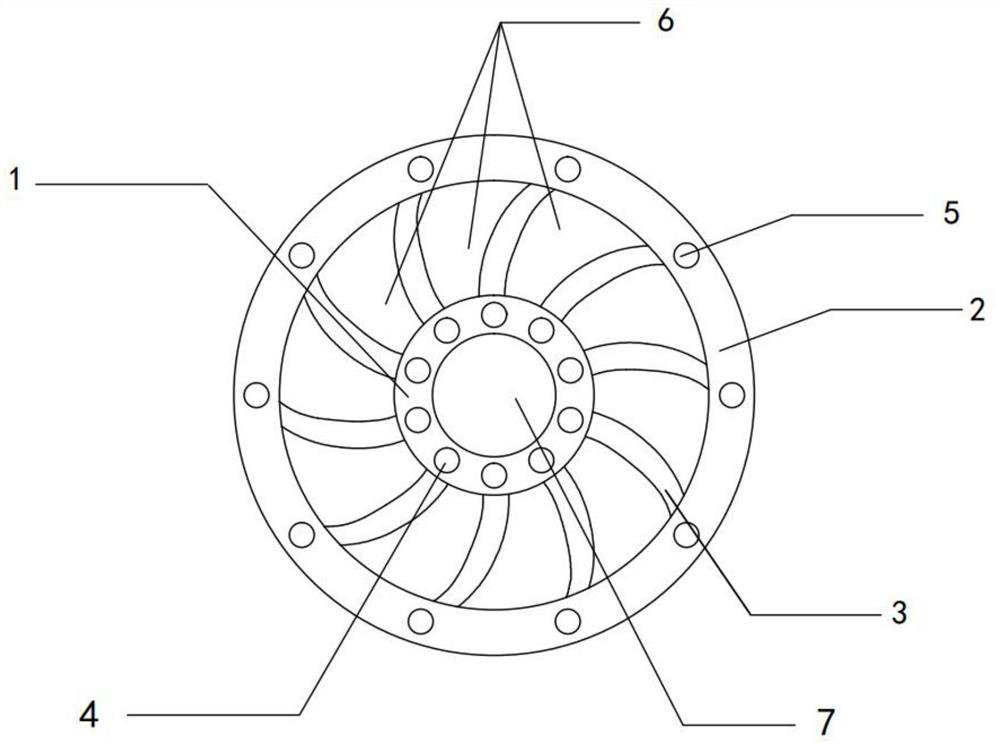
[0043] Based on the same technical concept as the above-mentioned embodiments, refer to figure 2As shown, in the fuel cell heat exchanger utilizing liquid hydrogen provided in this embodiment, the fins are arranged in a spoke-like arrangement between the inner ring and the outer ring, and the sides of the fins are curved surfaces. Among them, the curved surface has a preferred angle range, which can be designed according to the actual situation, such as 10°; the rotation angle of the curved surface increases the contact area on the one hand, and on the other hand can improve the convective heat transfer coefficient, thereby improving the heat transfer efficiency and further accelerating the air flow Cooling efficiency of the process.
[0044] Preferably, the fin includes an inner cavity, and a heat dissipation pipeline is arranged in the inner cavity, and the hydrogen outlet and the hydrogen inlet are respectively communicated with both ends of the heat dissipation pipeline. ...
Embodiment 3
[0046] Based on the same technical concept as the above-mentioned embodiment, in the fuel cell heat exchanger utilizing liquid hydrogen provided in this embodiment, the air flow cavity includes an air intake cavity and an air outlet cavity, and the air intake cavity is composed of the several The fins are closed with the casing, the air outlet cavity is communicated with the inner ring, a communication cavity is provided between the bottom of the fin and the bottom of the casing, and the air outlet cavity and the air inlet cavity are The air inlet and the air outlet are respectively arranged on the top of the casing.
[0047] In this embodiment, in the two parts of the air circulation cavity, the fins are arranged at one end inside the shell to form a sealed connection, so that an air outlet cavity connected to the inner ring is formed inside the shell to isolate the flow of air, and the air passes through the bottom The communication cavity of the two cavities conducts the fl...
PUM
 Abstract
Description
Claims
Application Information
 - R&D Engineer
- R&D Manager
- IP Professional
- Industry Leading Data Capabilities
- Powerful AI technology
- Patent DNA Extraction
Browse by: Latest US Patents, China's latest patents, Technical Efficacy Thesaurus, Application Domain, Technology Topic, Popular Technical Reports.
© 2024 PatSnap. All rights reserved.Legal|Privacy policy|Modern Slavery Act Transparency Statement|Sitemap|About US| Contact US: help@patsnap.com


