Automatic welding equipment for metal pipe fittings

A technology for automatic welding and metal pipe fittings, applied in the field of pipe fittings processing, can solve the problems of affecting welding accuracy, low efficiency, inconvenient large-scale use, etc., and achieve the effect of enhancing the fixing effect, increasing the contact area, and increasing the friction force

Inactive Publication Date: 2022-07-22
徐州好合智能装备有限公司
View PDF19 Cites 1 Cited by
  • Summary
  • Abstract
  • Description
  • Claims
  • Application Information

AI Technical Summary

Problems solved by technology

[0003] For the welding of pipe fittings, the existing welding equipment can only take out the pipe fittings after the pipe fittings are welded by opening the shell, which is not only inefficient, but also inconvenient for large-scale use in production
[0004] Aiming at the problem that the above-mentioned pipe fittings are difficult to take out, corresponding solutions are provided in the prior art, for example: the Chinese invention patent with the publication number CN105618946A discloses a pipe fitting welding machine, which passes between the upper clamping plate and the lower clamping plate The matching of the pipe fittings forms a clamping gap to realize the clamping of the pipe fittings, and then the pipe fittings are supported upwards by the welding plate. After the welding end of the pipe fittings is heated, the welding plate is removed, and then the pipe fittings are automatically welded, and finally the welding is completed automatically. The pipe fittings are ejected
[0005] However, the pipe fitting welding machine provided by the above-mentioned patent also has the following problems: 1. Since the outer wall of the pipe fitting is mostly a smooth arc surface, it is easy to reduce the friction between the pipe fitting and the upper clamping plate and the lower clamping plate, so that the pipe fitting lacks Stability, so that the pipe fittings are easy to rotate during the welding process, and it is easy to affect the welding effect of the pipe fittings
[0006] 2. Since the welded end of the pipe fitting needs to be removed after heating, the welded end of the pipe fitting cannot be supported and fixed, so that misalignment between the pipe fittings is likely to occur during the welding process, thereby affecting the welding accuracy

Method used


Image

  • Automatic welding equipment for metal pipe fittings
  • Automatic welding equipment for metal pipe fittings
  • Automatic welding equipment for metal pipe fittings

Examples


Embodiment Construction

[0032] Embodiments of the present invention are described in detail below with reference to the accompanying drawings, but the present invention can be implemented in many different ways as defined and covered by the claims.

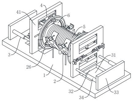
[0033] see figure 1 , an automatic welding equipment for metal pipe fittings, including a workbench 1, a support unit 2, a support unit 3 and a welding unit 4, a support unit 2 is installed in the middle of the upper end of the workbench 1, and the upper end of the workbench 1 is located in the support unit. The outer side of 2 is provided with a support unit 3, and a welding unit 4 is installed on the support unit 3.

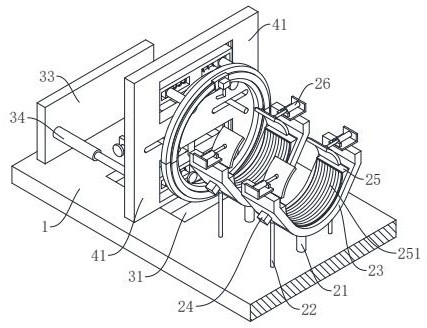
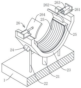
[0034] see figure 2 and image 3 , the support unit 2 includes a positioning column 21, a top extension column 22, a V-shaped frame 23, an air pump 24, an air bag 25 and a pressing component 26, wherein: the middle of the upper end of the workbench 1 is symmetrically arranged with two sets of support groups, Each support group includes ...


PUM


Abstract

The invention relates to the technical field of pipe fitting machining, in particular to metal pipe fitting automatic welding equipment which comprises a workbench, a supporting unit, a bearing unit and a welding unit. An existing welding machine has the following problems that friction force between an upper clamping plate and a lower clamping plate of the welding machine and a pipe fitting lacks, the pipe fitting lacks stability, the pipe fitting is prone to rotating in the welding process, and the welding effect on the pipe fitting is prone to being affected; the welding ends of the pipe fittings cannot be supported or fixed, so that the pipe fittings are prone to dislocation in the welding process, and then the welding precision is affected. The corrugated pipe can be fixed through an arc-shaped pressing plate and an attaching layer, a flange plate is fixed through a connecting column and a stabilizing belt, and the flange plate is prevented from shaking; the corrugated pipe and the flange plate can be in butt joint and fixed, and therefore the situation that the welding precision is affected due to dislocation between the corrugated pipe and the flange plate is prevented.

Description

technical field [0001] The invention relates to the technical field of pipe fittings processing, in particular to an automatic welding equipment for metal pipe fittings. Background technique [0002] Metal pipe fittings are a general term for the parts in the pipeline system that play the role of connection, control, direction change, shunt, sealing, and support. Among them, after the bellows is made, flanges need to be welded at its ends to facilitate the later connection and use of the bellows. [0003] As for the welding of pipe fittings, the existing welding equipment can only take out the pipe fittings by opening the shell after welding the pipe fittings, which is not only inefficient, but also inconvenient for large-scale use in production. [0004] In view of the problem that the pipe fittings are difficult to take out, corresponding solutions are provided in the prior art. For example, the Chinese invention patent with publication number CN105618946A discloses a pip...

Claims


Application Information

Patent Timeline
Patent Type & Authority Applications(China)
IPC IPC(8): B23K31/02B23K37/053B23K37/00
CPCB23K31/027B23K37/0533B23K37/00
Inventor 张新东
Owner 徐州好合智能装备有限公司
Why Eureka
Try Eureka