Novel water pump control system and control method
A control system and water pump technology, applied in the direction of pumps, pump components, non-variable-capacity pumps, etc., can solve the problems of low pump service life and inconvenient control of underground water pumps, so as to reduce workload, reduce cleaning workload, and reduce sewage. The effects of dealing with stress
- Summary
- Abstract
- Description
- Claims
- Application Information
AI Technical Summary
Problems solved by technology
Method used
Image
Examples
Embodiment 1
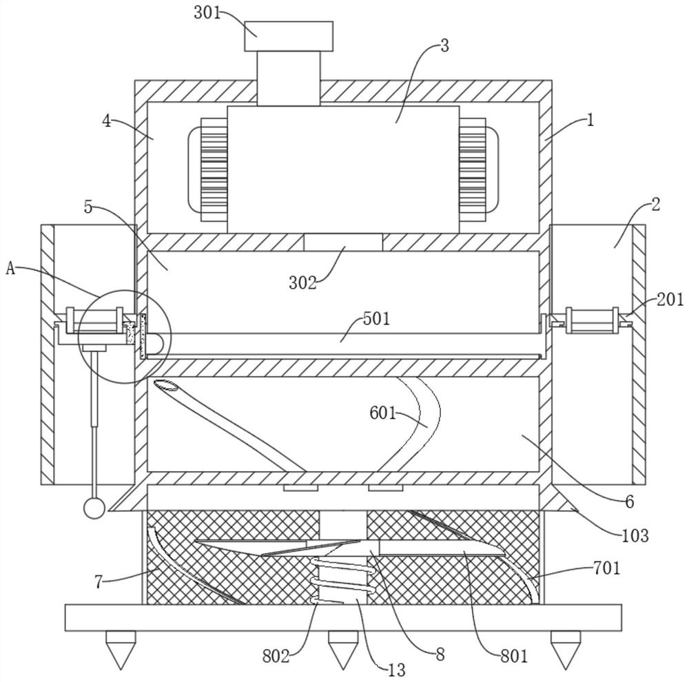
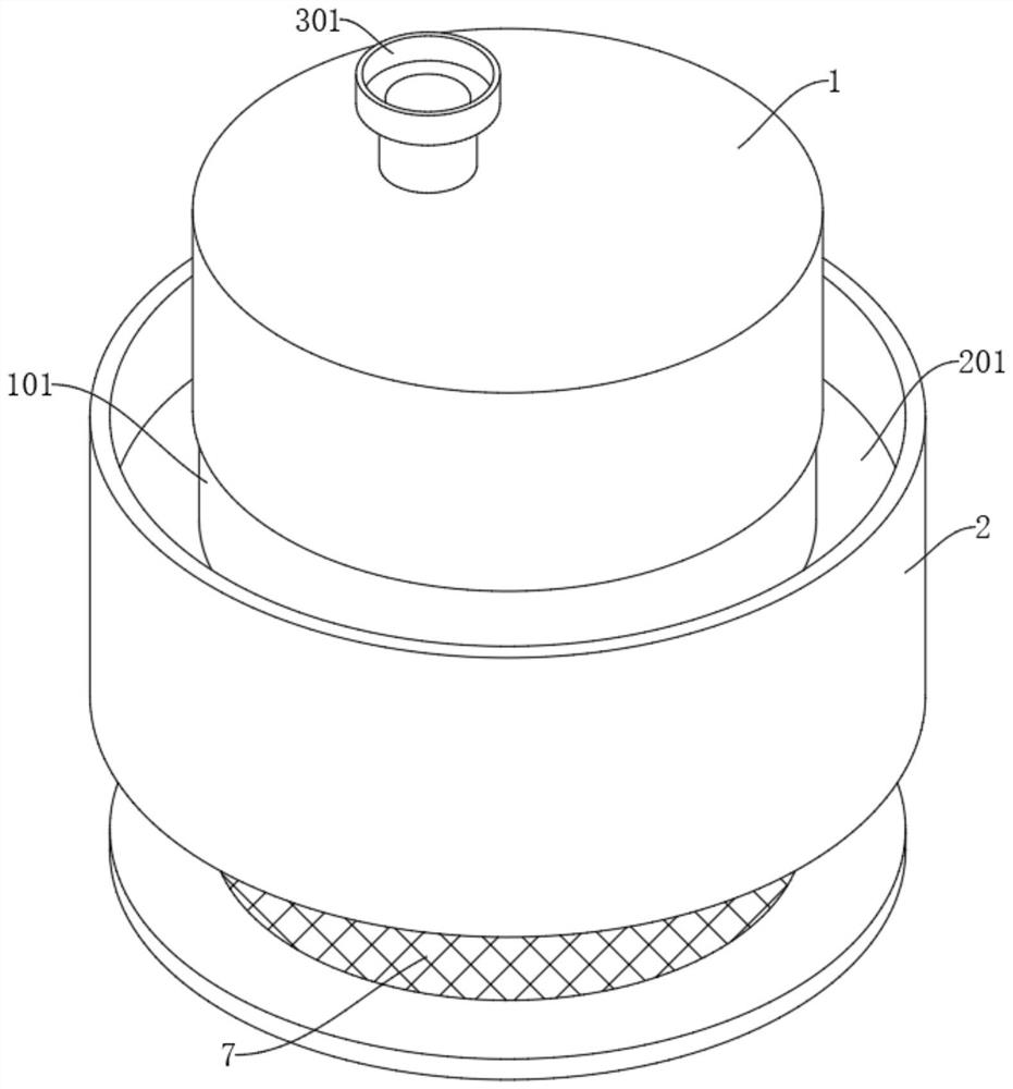
[0036] refer to figure 1 , image 3 and Figure 4 , a new type of water pump control system, including a pump body 3 and a control cylinder 1, the control cylinder 1 is provided with an installation cavity 4, a transfer cavity 5 and a control cavity 6 in order from top to bottom, and the pump body 3 is arranged in the installation cavity 4, It also includes: a plurality of sets of spiral water pipes 601 with solenoid valves, which are arranged in the control cavity 6; a sleeve 2 slidably arranged on the outer wall of the control cylinder 1, wherein the sleeve 2 is provided with a partition 201, and the partition 201 The bottom is slidably provided with a material-removing member, and a driving part for driving the material-removing member is arranged in the transfer cavity 5 .
[0037] When in use, place the control cylinder 1 in the place where the water accumulates in the mine, and ensure that the filter screen 7 is buried by the water body. It is advisable for the water l...
Embodiment 2
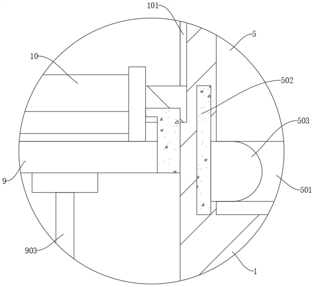
[0039] refer to figure 1 , figure 2 , image 3 , Figure 4 , Figure 5 and Image 6, a new type of water pump control system, including a pump body 3 and a control cylinder 1, the control cylinder 1 is provided with an installation cavity 4, a transfer cavity 5 and a control cavity 6 in order from top to bottom, and the pump body 3 is arranged in the installation cavity 4, It also includes: a plurality of sets of spiral water pipes 601 with solenoid valves, which are arranged in the control cavity 6; a sleeve 2 slidably arranged on the outer wall of the control cylinder 1, wherein the sleeve 2 is provided with a partition 201, and the partition 201 The bottom is slidably provided with a material-removing member, and a driving part for driving the material-removing member is arranged in the transfer cavity 5. When the material-removing member is moved, the partition plate 201 is turned on; the filter screen 7 arranged at the bottom of the control cylinder 1, but On this b...
Embodiment 3
[0042] refer to figure 1 , image 3 and Figure 4 , a new type of water pump control system, including a pump body 3 and a control cylinder 1, the control cylinder 1 is provided with an installation cavity 4, a transfer cavity 5 and a control cavity 6 in order from top to bottom, and the pump body 3 is arranged in the installation cavity 4, It also includes: a plurality of sets of spiral water pipes 601 with solenoid valves, which are arranged in the control cavity 6; a sleeve 2 slidably arranged on the outer wall of the control cylinder 1, wherein the sleeve 2 is provided with a partition 201, and the partition 201 The bottom is slidably provided with a feeding piece, and a driving part for driving the action of the feeding piece is arranged in the transfer cavity 5. When the feeding piece moves, the baffle 201 is turned on; , we add a positioning column 13 fixed at the bottom of the control cylinder 1, the filter screen 7 covers the positioning column 13; a slip ring 8 is ...
PUM
 Abstract
Description
Claims
Application Information
 - R&D
- Intellectual Property
- Life Sciences
- Materials
- Tech Scout
- Unparalleled Data Quality
- Higher Quality Content
- 60% Fewer Hallucinations
Browse by: Latest US Patents, China's latest patents, Technical Efficacy Thesaurus, Application Domain, Technology Topic, Popular Technical Reports.
© 2025 PatSnap. All rights reserved.Legal|Privacy policy|Modern Slavery Act Transparency Statement|Sitemap|About US| Contact US: help@patsnap.com


