
Centrifugal air purifier

An air purifier and centrifugal technology, applied in the field of centrifugal air purifiers, can solve the problems of rising cost and high energy consumption, and achieve the effects of increasing airflow density, prolonging reaction time, and high-efficiency purification effect.

Pending Publication Date: 2022-07-22
张洛维
View PDF0 Cites 0 Cited by
  • Summary
  • Abstract
  • Description
  • Claims
  • Application Information

AI Technical Summary

Problems solved by technology

[0004] The invention provides a centrifugal air purifier, which is used to solve the defect that the purification effect of the photocatalyst purification device in the prior art depends on the length of the air duct, which leads to high energy consumption and increased costs, and realizes that it does not increase the physical structure of the photocatalyst purification device. The purpose of effectively improving the purification effect and reducing energy consumption and cost on the basis of

Method used


Image

  • Centrifugal air purifier
  • Centrifugal air purifier
  • Centrifugal air purifier

Examples


Embodiment Construction

[0028] In order to make the objectives, technical solutions and advantages of the present invention clearer, the technical solutions in the present invention will be clearly and completely described below with reference to the accompanying drawings. Obviously, the described embodiments are part of the embodiments of the present invention. , not all examples. Based on the embodiments of the present invention, all other embodiments obtained by those of ordinary skill in the art without creative efforts shall fall within the protection scope of the present invention.

[0029] In the description of the embodiments of the present invention, it should be noted that the terms "center", "portrait", "horizontal", "top", "bottom", "front", "rear", "left", "right" , "vertical", "horizontal", "top", "bottom", "inside", "outside", etc. indicate the orientation or positional relationship based on the orientation or positional relationship shown in the accompanying drawings, only for the con...


PUM


Abstract

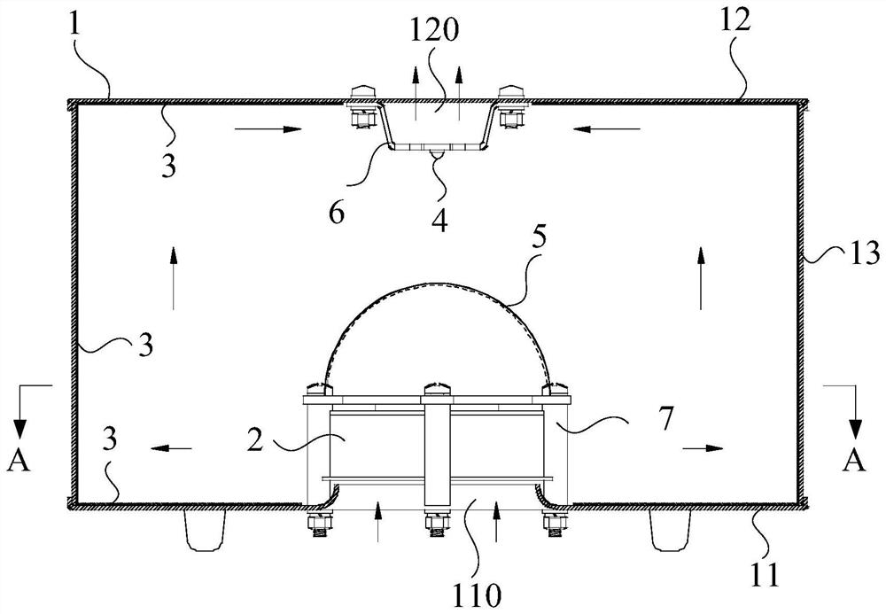
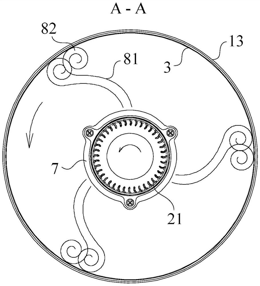
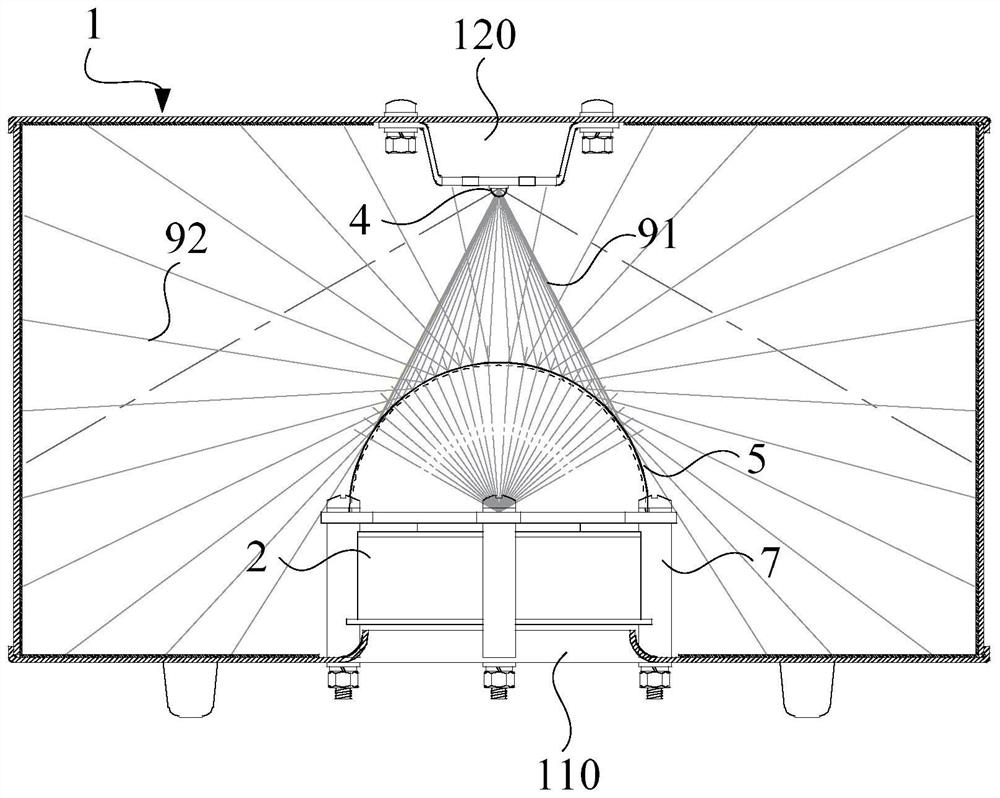
According to the centrifugal air purifier, a cylindrical inner cavity is formed in a shell, an air inlet is formed in one end of the cylindrical inner cavity, an air outlet is formed in the other end of the cylindrical inner cavity, a centrifugal fan is arranged in the cylindrical inner cavity, the air inlet side of the centrifugal fan is right opposite to the air inlet, and the air outlet side of the centrifugal fan is distributed on the peripheral wall of the centrifugal fan; the air outlet side corresponds to the inner peripheral wall of the cylindrical inner cavity; the photocatalyst carrier is arranged on the surface of the inner wall of the barrel-shaped inner cavity, and the ultraviolet light source is arranged in the barrel-shaped inner cavity and used for irradiating the photocatalyst carrier. By means of the centrifugal fan and the cylindrical inner cavity, air rotates at a high speed to generate centrifugal force, pollutants carried in the air are compressed on the surface of the photocatalyst carrier on the inner wall of the device, and the decomposition and disinfection efficiency can be improved; under the action of frictional resistance of the surface of the photocatalyst carrier, a continuous rolling forward vortex is generated, so that more gaseous pollutants can be captured by the photocatalyst, and the purification efficiency is improved.

Description

technical field [0001] The invention relates to the technical field of air purifiers, in particular to a centrifugal air purifier. Background technique [0002] In air purifiers, photocatalyst catalytic decomposition is a common technology to remove harmful chemical gaseous pollutants in the air. The principle is that under the irradiation of light, the surface of the photocatalyst produces pairs of holes and electrons. When water molecules in the air contact it, hydroxyl radicals are rapidly generated and attached to the surface. As a strong oxidant, this substance can decompose harmful chemical gaseous pollutants in the air. The reaction produces harmless water and carbon dioxide. Hydroxyl free radicals can also coagulate viral proteins and destroy bacterial cell walls, thereby purifying the air. This kind of purifier device usually attaches the photocatalyst carrier to the surface of a certain substrate. During operation, the air must fully contact the photocatalyst car...

Claims


Application Information

Patent Timeline
IPC IPC(8): F24F8/167F24F8/22F24F13/20F24F13/32
CPCF24F8/167F24F8/22F24F13/20F24F13/32
Inventor 张洛维
Owner 张洛维
Learn More