
Continuous multi-chamber heat treatment furnace and treatment process thereof

A technology for heat treatment furnaces and heating furnaces, applied in heat treatment furnaces, heat treatment equipment, heat treatment process control, etc., can solve the problems of long temperature rise time, high energy consumption, inconsistent cooling speed of billets, etc., and achieve low energy consumption, high efficiency, Fast heating effect

Pending Publication Date: 2022-07-29
杭州科德磁业有限公司
View PDF5 Cites 0 Cited by
  • Summary
  • Abstract
  • Description
  • Claims
  • Application Information

AI Technical Summary

Problems solved by technology

[0005] In view of the above-mentioned problems, the present invention provides a multi-chamber heat treatment furnace and its treatment process to solve the following problems in the existing heat treatment process: 1. Solve the problems of long temperature rise time and high energy consumption in the heat treatment of the billet; Inconsistent cooling rate issues
3. Solve the problem that the billet cannot be continuously heat treated and the efficiency is low

Method used


Image

  • Continuous multi-chamber heat treatment furnace and treatment process thereof
  • Continuous multi-chamber heat treatment furnace and treatment process thereof
  • Continuous multi-chamber heat treatment furnace and treatment process thereof

Examples


Embodiment Construction

[0042] The technical solutions in the embodiments of the present invention will be clearly and completely described below. Obviously, the described embodiments are only a part of the embodiments of the present invention, rather than all the embodiments. Based on the embodiments of the present invention, all other embodiments obtained by those of ordinary skill in the art without creative efforts shall fall within the protection scope of the present invention.

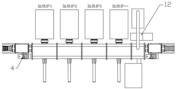
[0043] like Figure 2-5 As shown, a continuous multi-chamber heat treatment furnace of the present invention mainly includes an inlet conveyor 1, an inlet exhaust chamber 3, a vacuum pump 4, a plurality of heating furnace units 6, a vacuum pump assembly 7, an outlet exhaust chamber 9, and an outlet conveyor. 11. The air cooling unit 12 and the control system are composed.

[0044] A plurality of heating furnace units 6 are arranged in parallel to form a heating furnace assembly. A first plug-in valve 2 is flange-sealed...


PUM


Abstract

The heat treatment furnace comprises a heating furnace assembly composed of a plurality of heating furnace units arranged in parallel, the feeding end of the heating furnace assembly is connected with an inlet exhaust bin, and the inlet exhaust bin is connected with an inlet conveyor; the discharging end of the heating furnace assembly is sequentially connected with an air cooling unit and an outlet exhaust bin, the outlet exhaust bin is connected with an outlet conveyor, the inlet exhaust bin and the outlet exhaust bin are respectively connected with a vacuum pump through pipelines, the heating furnace assembly is connected with the vacuum pump assembly, and the multi-chamber heat treatment furnace further comprises a control system. The invention further discloses a treatment process of the heat treatment furnace. According to the scheme, the heating furnace does not need to be repeatedly cooled and heated, the energy consumption is greatly reduced, the blank heating speed is higher, and the efficiency is higher; in addition, cold air blows small batches of blanks from top to bottom, and the cooling speed is consistent; according to the invention, an automatic control technology is used, and a conveyor and a transfer mechanism are matched to realize continuous heat treatment and non-stop work.

Description

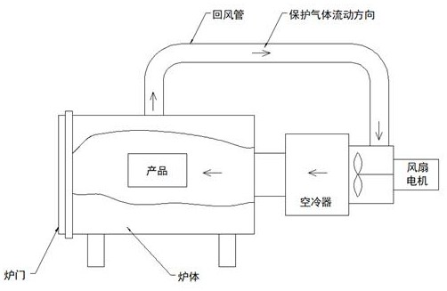
technical field [0001] The invention belongs to the technical field of heat treatment furnaces, in particular to a multi-chamber heat treatment furnace and a treatment process thereof. Background technique [0002] Existing heat treatment equipment such as figure 1 As shown, it is composed of furnace body, furnace door, return air duct, fan, air cooler, vacuum pump, control cabinet and other main parts. The process of billet heat treatment is as follows: 1. The billet (about 200Kg) is placed in the furnace body, and the furnace door is closed; 2. The air in the furnace body is evacuated by a vacuum pump to a vacuum, and then an inert protective gas is injected. The purpose is to prevent the billet from contacting with oxygen or other gases that are prone to chemical reaction of the billet during the heating process; 3. After heating to the set time, the billet is cooled by air. The fan pressurizes the hot air drawn from the return air pipe, cools it through the air cooler,...

Claims


Application Information

Patent Timeline
Patent Type & Authority Applications(China)
IPC IPC(8): C21D9/00C21D1/74C21D1/773C21D11/00
CPCC21D9/0062C21D9/0018C21D9/0025C21D1/74C21D1/773C21D11/00
Inventor 张保国杨全福刘正兴付勇兵向俊尤丁杰
Owner 杭州科德磁业有限公司
Learn More