Thermal decomposition tube with fluid stirring element

A stirring element and thermal decomposition technology, applied in tubular elements, heat exchange equipment, non-catalytic thermal cracking, etc., can solve problems such as heating and boundary film formation, and achieve the goals of suppressing gap filling, increasing yield, and improving heat transfer efficiency Effect

Pending Publication Date: 2022-07-29
KUBOTA LTD
View PDF1 Cites 0 Cited by
  • Summary
  • Abstract
  • Description
  • Claims
  • Application Information

AI Technical Summary

Problems solved by technology

However, the fluid is stirred at the protruding part, but it flows along the inner surface of the tube in the part where the protruding part is not formed, and there is a possibility that a boundary f

Method used


Image

  • Thermal decomposition tube with fluid stirring element
  • Thermal decomposition tube with fluid stirring element
  • Thermal decomposition tube with fluid stirring element

Examples


no. 1 Embodiment >

[0048] like Figure 4 As shown in the figure, a run-up section 31 having a 1.6 m upstream side and a downstream side of figure 1 The thermal decomposition tube 10 of the illustrated example of the invention having a length of 0.6 m, or Figure 5 The test thermal decomposition tube 30 to which the thermal decomposition tube 40 of the comparative example having a length of 0.6 m shown was connected, was compared by measuring the outlet temperature (° C.) and the heat exchange amount (kW) by circulating a fluid. The inner diameter of the thermal decomposition tubes 10 and 40 was 40 mm.

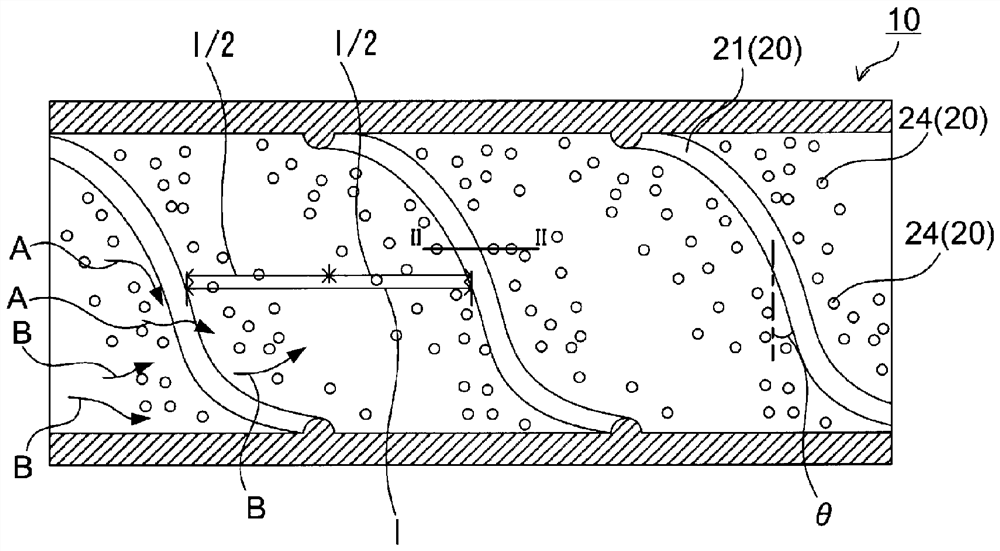
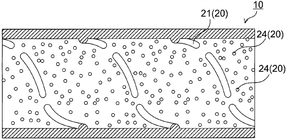
[0049] The thermal decomposition tube 10 of the invention example is as figure 1 As shown, a continuous one spiral ridge 21 is formed as a stirring element inside, and a plurality of protrusions 24 are formed on the peripheral portion thereof. In addition, the thermal decomposition tube 40 of the comparative example is as Figure 5 As shown, only one continuous spiral ridge 21 is formed insid...

no. 2 Embodiment >

[0056] The inner surface of a thermal decomposition tube with an inner diameter of 40 mm and a length of 0.6 mm is fabricated as follows Image 6 As shown in (a) to (f), the invention examples 1 to 6 in which the protrusions 21 and the protrusions 24 are formed are as follows: Image 6 In Comparative Examples 1 and 2 in which only the protrusions 21 are formed as shown in (g), the outlet temperature (° C.), pressure loss (Pa) and heat transfer coefficient (W / m) of the fluid were measured by circulating air inside. 2 K).

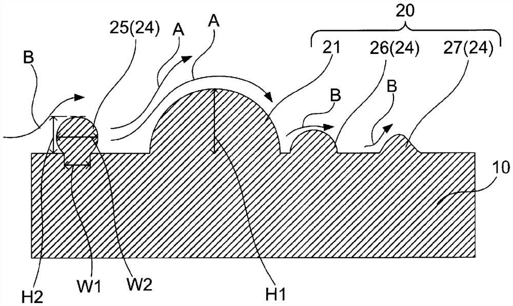
[0057] In each of the invention examples and the comparative examples, the spiral protrusions 21 having an inclination angle θ of 30° and a width of 7.0 mm were formed. The heights of the protrusions 21 of Invention Examples 1 to 6 and Comparative Example 1 were 2.1 mm, and the height of the protrusions 21 of Comparative Example 2 was 1.5 mm.

[0058] In the invention example, the hemispherical protrusions 24 having a diameter of 2.0 mm and a height of 1.0 ...


PUM

PropertyMeasurementUnit
The inside diameter ofaaaaaaaaaa

Abstract

Provided is a thermal decomposition tube which has an effect of stirring a fluid in the tube and which is capable of preventing overheating due to the occurrence of laminar flow. This thermal decomposition tube (10) provided with stirring elements (20) is configured in such a manner that one or more fluid stirring elements protrude inward on the inner surface of the tube, and the stirring elements comprise: protrusions (21) that extend along the inner surface of the tube and that protrude inward from the inner surface of the tube, and protrusions (24) that protrude inward from the inner surface of the tube and that protrude inward from the inner surface of the tube; the protrusions (24) protrude inward from the inner surface of the tube at the peripheral portions of the ridges. The peripheral portion of the ridge preferably includes the upstream side and/or the downstream side of the ridge in the direction in which fluid flows in the pipe.

Description

technical field [0001] The present invention relates to a thermal decomposition tube used in a thermal decomposition reactor for the production of ethylene and the like, and more particularly, to a thermal decomposition tube in which a stirring element for enhancing the stirring effect of the fluid in the tube is protruded from the inner surface of the tube. Background technique [0002] Olefins such as ethylene and propylene are produced by passing a raw material fluid including hydrocarbons (naphtha, natural gas, ethane, etc.) at a high speed through a thermal decomposition tube heated from the outside, heating the raw material fluid to a reaction temperature range, and thermally decomposing it. [0003] In order to efficiently carry out the thermal decomposition reaction, it is important to heat the high-speed raw material fluid to the radial center portion of the pipeline to the thermal decomposition reaction temperature region in a short time, and to avoid overheating as...

Claims


Application Information

Patent Timeline
IPC IPC(8): F28F1/40
CPCF28F1/40C10G9/16C10G9/20F28D2021/0075
Inventor 松原基行桥本国秀
Owner KUBOTA LTD
Why Eureka
Try Eureka