Automatic adjusting system for indoor temperature of transformer substation

An indoor temperature and automatic adjustment technology, applied in the field of substations, can solve the problems of limited location of vents, poor ventilation and heat dissipation, and poor local ventilation and heat dissipation, so as to reduce equipment load loss, increase equipment load capacity, The effect of improving the operating environment

Pending Publication Date: 2022-08-05
STATE GRID TIANJIN ELECTRIC POWER +1
0 Cites 0 Cited by

AI-Extracted Technical Summary

Problems solved by technology

At noon is the heat dissipation peak time of transformers and other equipment, and it is also the peak time of outdoor ambient temperature. The temperature difference between the air sucked in from the air inlet at the low position of the equipment room and the air discharged from the top becomes smaller, resulting in poor ventilation and heat dissipation. Even if the axial flow fan is used for mechanical exhaust, the effect is not significant
Due to the compact layout of indoo...

Abstract

The invention relates to a transformer substation indoor temperature automatic adjusting system, which comprises a photovoltaic power generation assembly, a photovoltaic junction box, an inverter, a variable frequency water pump, a water cooling machine and a cooling device, and is characterized in that the photovoltaic power generation assembly is arranged at the top of a transformer substation, and the photovoltaic junction box is arranged at a position close to the photovoltaic power generation assembly; the inverter, the water cooling machine and the variable frequency water pump are arranged in a pump room, and the cooling devices are arranged in a transformer substation room and used for automatically adjusting the temperature in the transformer substation room. Through the method of circulating cold water cooling and air convection heat dissipation, the operation environment of indoor equipment is improved, then the effects of prolonging the operation life of the indoor equipment, increasing the load capacity of the equipment and reducing the load loss of the equipment are achieved, and meanwhile the problem that the local ventilation heat dissipation effect of the equipment is poor due to the fact that the position of an air inlet is limited is solved.

Application Domain

Technology Topic

Load lossEngineering +8

Image

  • Automatic adjusting system for indoor temperature of transformer substation
  • Automatic adjusting system for indoor temperature of transformer substation
  • Automatic adjusting system for indoor temperature of transformer substation

Examples

  • Experimental program(1)

Example Embodiment

[0029] The present invention will be described in further detail below in conjunction with the accompanying drawings.
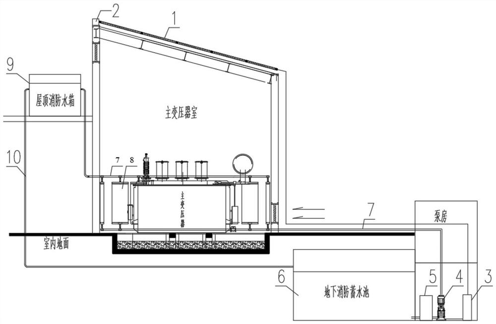
[0030] It should be noted that due to the fire management requirements of the substation, the substation is usually provided with an underground fire fighting reservoir 6 and a roof fire fighting water tank 9 and a pump room matched with the underground fire fighting reservoir 6, and the underground fire fighting reservoir 6 and the roof fire fighting water tank 9. There is a large amount of water stored in the substation. Through these existing equipment resources and water resources, an effective heat exchange is formed, which improves the operating environment of the indoor equipment of the substation, thereby improving the operating life of the indoor equipment in the substation, increasing the load capacity of the equipment, and reducing the load loss of the equipment. effect,
[0031] The present invention proposes a substation indoor temperature automatic adjustment system, such as figure 1 As shown, it includes a photovoltaic power generation assembly 1, a photovoltaic junction box 2, an inverter 3, a variable frequency water pump 4, a water cooler 5 and a cooling device 8,
[0032] The photovoltaic power generation assembly 1 is arranged on the top of the substation and is used to convert light energy into electrical energy,
[0033] The photovoltaic junction box 2 is arranged near the photovoltaic power generation assembly 1 and is used to transmit the converted electric energy to the inverter 3,
[0034] The inverter 3 is arranged in the pump room and is used to convert the direct current into alternating current to push the variable frequency water pump 4 to work,
[0035] The variable frequency water pump 4 is arranged in the pump room and is used to realize the circulation of the water source inside the outdoor fire fighting reservoir 6 and the roof fire fighting water tank 9 in the cooling device 8,
[0036] The cooling devices 8 are arranged in at least two groups and are installed in the substation room for automatic adjustment of the internal temperature of the substation room;
[0037] The water cooler 5 is arranged in the pump room, the water inlet end of the water cooler 5 is connected to the underground fire fighting reservoir 6, and the water outlet end is connected to the variable frequency water pump 4. The water cooler 5 is started by water flow and is used for The water in the underground fire fighting reservoir 6 is rapidly cooled and flows into the cooling device 8 through the variable frequency water pump 4,
[0038] In this embodiment, a water inlet pipe 7 is arranged between the variable frequency water pump 4 , the cooling device 8 and the roof fire fighting water tank 9 , and a return water pipe 10 is arranged between the roof fire fighting water tank 9 and the outdoor fire fighting reservoir 6 .
[0039] In this embodiment, the cooling device 8 includes a temperature guide tube 12 , a cooling fin 13 and a cooling connection piece 14 . The temperature guide tube 12 is arranged in a wave shape and two ends are connected to the cooling connection piece 14 respectively. The water inlet pipe 7 communicates with each other, the cooling fins 13 are semi-open structures and the temperature guide pipes 12 are arranged inside the semi-open structure, and the cooling fins 13 are used to enlarge the temperature guide pipes. 12. The contact area with the surrounding air uses the temperature difference between the cold water flow and the hot air to effectively reduce the surrounding air temperature.
[0040] In this embodiment, the material of the heat conducting pipe 12 is copper, and the cooling fin radiator 13 is made of a heat conducting material.
[0041] In this embodiment, the movement process of the indoor temperature automatic adjustment system of the substation is specifically:
[0042] As the solar radiation heat increases, the indoor temperature of the substation increases and the power generation of the photovoltaic power generation assembly 1 increases. When the power generation power of the photovoltaic power generation assembly 1 is greater than the preset power of the variable frequency water pump 4, the variable frequency water pump 4. At the same time, the water flow of the water cooler 5 is driven to start, and the water sources inside the outdoor fire fighting reservoir 6 and the roof fire fighting water tank 9 are circulated through the cooling device 8;
[0043] As the solar radiation heat decreases, the indoor temperature of the substation decreases and the power generation of the photovoltaic power generation assembly 1 decreases. When the power generation power of the photovoltaic power generation assembly 1 is less than the preset power of the variable frequency water pump 4, the variable frequency water pump 4. At the same time, the water cooler 5 stops working, and the water sources inside the outdoor fire-fighting reservoir 6 and the roof fire-fighting water tank 9 stop circulating in the cooling device 8.
[0044] The relative steps, numerical expressions and numerical values ​​of the components and steps set forth in these embodiments do not limit the scope of the invention unless specifically stated otherwise.
[0045]Those skilled in the art can clearly understand that, for the convenience and brevity of description, for the specific working process of the system and device described above, reference may be made to the corresponding process in the foregoing method embodiments, which will not be repeated here.
[0046] To sum up, the content of the present invention is not limited to the above-mentioned embodiments, and those skilled in the art can propose other embodiments within the technical guidance of the present invention, but these embodiments are all included in the present invention. within the range.
[0047] It should be emphasized that the embodiments described in the present invention are illustrative rather than restrictive, so the present invention includes but is not limited to the embodiments described in the specific implementation manner. Other embodiments derived from the scheme also belong to the protection scope of the present invention.

PUM

no PUM

Description & Claims & Application Information

We can also present the details of the Description, Claims and Application information to help users get a comprehensive understanding of the technical details of the patent, such as background art, summary of invention, brief description of drawings, description of embodiments, and other original content. On the other hand, users can also determine the specific scope of protection of the technology through the list of claims; as well as understand the changes in the life cycle of the technology with the presentation of the patent timeline. Login to view more.

Similar technology patents

Device for isolating indoor and outdoor air and synchronously generating ions

PendingCN110805971AImprove the effectiveness of insulationImprove the operating environmentMechanical apparatusLighting and heating apparatusSewageOxygen ions
Owner:SHANGHAI MUNICIPAL ENG DESIGN INST GRP

Classification and recommendation of technical efficacy words

  • Increased operating life
  • Improve the operating environment

Seal Arrangement for a Rotating Ship Propeller Shaft

InactiveUS20140048461A1Increased operating lifeRobust and highly effective and functional arrangementEngine sealsMachines/enginesPropellerFuel tank
Owner:BLOHM VOSS IND

Reclaiming agent, reclaimed rubber prepared therefrom, and preparation method of reclaimed rubber

InactiveCN103435843AImprove the operating environmentGet rid of bad smell and pollutionPlastic recyclingChemistryCrumb rubber
Owner:CHINA RUBBER RESOURCE REGENERATION QINGDAO
Why Eureka
Try Eureka