Method for measuring current of switch integrated into power module

A technology of power modules and switching currents, which is applied to the components of electrical measuring instruments, measuring electronics, and measuring devices. It can solve the problems of uneven winding, large volume, and uneven winding, and achieve compact structure, small volume, and The effect of improving the difficulty and accuracy

Pending Publication Date: 2022-08-09
HEBEI UNIV OF TECH
View PDF0 Cites 0 Cited by
  • Summary
  • Abstract
  • Description
  • Claims
  • Application Information

AI Technical Summary

Problems solved by technology

[0005] Aiming at the deficiencies of the prior art, the technical problem to be solved by the present invention is to provide a switching current measurement method integrated into the power module, the Rogowski coil is integrated into the power module, and the output terminal of the Rogowski coil is connected to the processing outside the power module Circuit connection, designed to solve the problem of difficult integration of existing Rogowski coil broadband and current sensors
The traditional Rogowski coil is wound on a non-magnetic skeleton, and there are problems such as uneven winding and large volume. In this application, two Rogowski coils are used to form a differential Rogowski coil, which can well solve the problem of uneven winding, and Small size, compact structure and easy integration, which improves the anti-interference performance of the current sensor

Method used


Image

  • Method for measuring current of switch integrated into power module
  • Method for measuring current of switch integrated into power module
  • Method for measuring current of switch integrated into power module

Examples


Embodiment Construction

[0060] The technical solutions of the present invention will be described in detail below with reference to the accompanying drawings and specific embodiments, but this does not limit the protection scope of the present application.

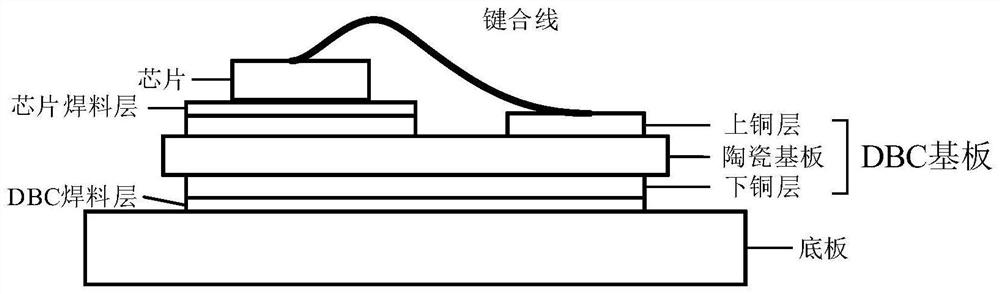
[0061] image 3 It is the internal packaging structure of the power module, including the bottom plate, the DBC substrate and the chip. The DBC substrate is composed of an upper copper layer, a ceramic substrate and a lower copper layer. The DBC substrate is welded on the bottom plate through the DBC solder layer, and the chip is welded on the top through the chip solder layer On the copper layer; the upper copper layer of the DBC substrate is generally provided with an island structure, and the power module can be an IGBT power module, a SiCMOSFET power module, or a SiC JFET power module.

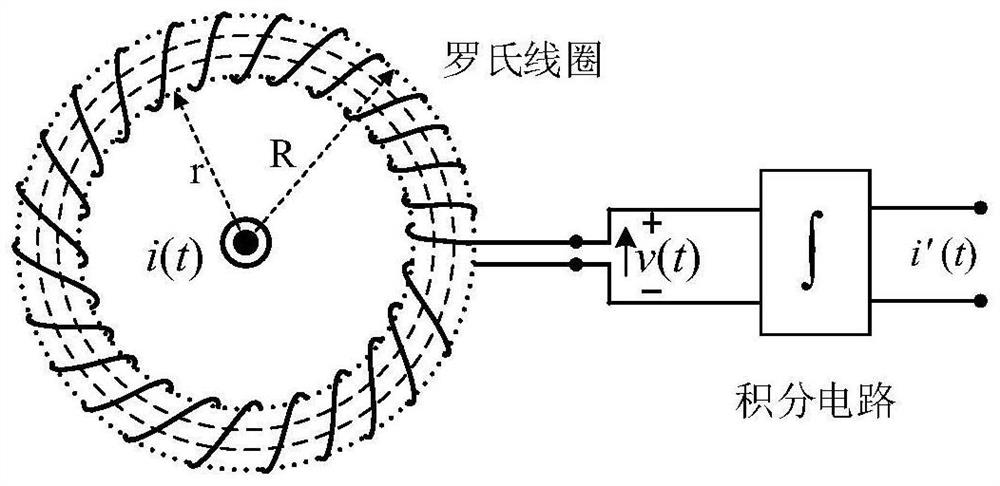
[0062] The present invention is a switch current measurement method integrated into the power module, such as Figure 4 As shown in the figure, the current ...


PUM


Abstract

The invention relates to a method for measuring current of a switch integrated into a power module. A current sensor used in the method comprises a Rogowski coil and a processing circuit. The two Rogowski coils are integrated in the power module to form a differential Rogowski coil, the processing circuit is located outside the power module, the output ends of the two Rogowski coils are connected with the input end of the processing circuit, and the grounding ends of the two Rogowski coils are connected with the grounding end of the processing circuit; the Rogowski coil is etched on an island structure of a copper layer on a DBC substrate of an internal packaging structure of the power module in a plane mode, the Rogowski coil is not electrically connected with the copper layer on the DBC substrate, and a current-carrying conductor of a tested switching current of the power module is located above the Rogowski coil and is not in contact with the Rogowski coil. The two Rogowski coils are symmetrically located on the two sides of the current-carrying conductor. On the premise that an existing packaging structure of the power module is not changed, the Rogowski coil is integrated into the power module only by changing partial structural layout, and the problem that an existing Rogowski coil broadband and a current sensor are difficult to integrate is solved.

Description

technical field [0001] The invention belongs to the technical field of switch current measurement, in particular to a switch current measurement method integrated into a power module. Background technique [0002] Current sensors play a vital role in modern power electronic systems, and the switching current information of power devices is a common key information required for power electronic fault protection, health monitoring and control. At present, extensive research work has been carried out on current sensing technology in power electronic systems, which can measure current through shunts, current transformers, Rogowski coils, Hall sensors, and magnetoresistive sensors. [0003] Shunts are the most cost-effective, and although their operation is simple based on Ohm's law, practical current shunts have inherent inductance, which limits their measurement accuracy and bandwidth (from DC to tens of MHz); furthermore, at high frequencies Due to the influence of the skin e...

Claims


Application Information

Patent Timeline
Patent Type & Authority Applications(China)
IPC IPC(8): G01R19/00G01R15/18G01R1/30
CPCG01R19/0092G01R15/181G01R1/30
Inventor 辛振蒙慧石亚飞康建龙
Owner HEBEI UNIV OF TECH
Why Eureka
Try Eureka