Coaxial cable manufacturing process and equipment

A technology for manufacturing equipment and coaxial cables, applied in the field of coaxial cable manufacturing process and equipment, can solve the problems of the outer sheath of the cable being easily damaged and broken, affecting the processing quality of the cable, etc., to achieve the effect of energy saving and improving the cleanliness of the equipment

Pending Publication Date: 2022-08-09
江苏亿通线缆有限公司
View PDF1 Cites 1 Cited by
  • Summary
  • Abstract
  • Description
  • Claims
  • Application Information

AI Technical Summary

Problems solved by technology

[0004] In the prior art, after the preparation of the coaxial cable is completed, the cable needs to be retracted to form a cable coil. However, when the existing retracting device initially retracts the cable, its surface is exposed to the outside world for a long time. environment, and some hard debris impurities are easy to adhere to, which makes the cable easy to be rigidly squeezed with the debris when it is retracted, causing the outer sheath of the cable to be easily damaged and ruptured, thus affecting the processing quality of the cable

Method used


Image

  • Coaxial cable manufacturing process and equipment
  • Coaxial cable manufacturing process and equipment
  • Coaxial cable manufacturing process and equipment

Examples


Embodiment 1

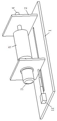
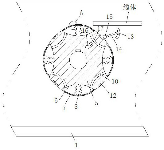
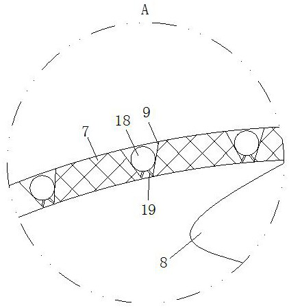
[0033] see Figure 1-Figure 2 As shown, a coaxial cable manufacturing equipment according to an embodiment of the present invention includes a bottom plate 1; a pair of support plates 2 are connected on the top surface of the bottom plate 1, and a motor 3 is installed on the plate surface of one support plate 2 , the output end of the motor 3 is connected with a rotating rod 4, and the other end of the rotating rod 4 extends to another support plate 2 and is connected with it in rotation. The rotating rod 4 is provided with a reel 5, so Several groups of grooves 6 are opened on the outer ring side wall of the take-up drum 5, and the outer end of the side wall of the groove 6 is connected with a bulging elastic film 7, and the elastic film 7 and the inner end of the groove 6 are connected. An elastic member 8 is connected between, and the surface of the elastic film 7 is provided with a number of air outlet holes 9; after the preparation of the coaxial cable in the prior art, t...

Embodiment 2

[0041] like Figure 4 As shown, Comparative Example 1, in which another embodiment of the present invention is: the side wall of the take-up drum 5 is provided with a slot 20, and the outer end of the side wall of the slot 20 is symmetrically provided with a chute , a slide plate 21 that is slidably connected to the side wall of the chute, a spring is connected between the slide plate 21 and the inner end of the chute, and the inner end of the chute is installed with a sliding plate 21 capable of attracting The electromagnet 22, an elastic tympanic membrane 23 is connected to the side wall of the inner end of the tympanic membrane 23, and the side wall of the tying slot 20 inside the tympanic membrane 23 is provided with a conducting groove 24 that communicates with the inner end of the chute; During the initial winding, the two electromagnets 22 can attract the slide plate 21 to make the card slot 20 open, and then the end of the cable body is placed inside the card slot 20. ...


PUM


Abstract

The invention belongs to the technical field of cables, and particularly relates to a coaxial cable manufacturing process and equipment. A pair of supporting plates is connected to the top face of the bottom plate, a motor is installed on the plate face of one supporting plate, the output end of the motor is connected with a rotating rod, a furling barrel is arranged on the rotating rod, a plurality of sets of grooves are formed in the outer ring side wall of the furling barrel, and bulged elastic films are connected to the outer ends of the side walls of the grooves. An elastic piece is connected between the elastic film and the inner end of the groove, and a plurality of air outlet holes are formed in the surface of the elastic film; according to the cable winding device, an elastic film can be extruded by a cable body, air can be blown to the side wall of the winding drum, impurities attached to the surface of the elastic film are blown off, and the situation that the cable body is deformed and broken due to rigid extrusion with the impurities on the side wall of the winding drum in the winding process is reduced; and an electric jet cleaning device is not required to be additionally arranged, so that the equipment is more energy-saving.

Description

technical field [0001] The invention belongs to the technical field of cables, in particular to a manufacturing process and equipment of a coaxial cable. Background technique [0002] Coaxial cable is a kind of wire and signal transmission line, which is generally made of four layers of materials: the innermost is a conductive copper wire, the outside of the wire is surrounded by a layer of plastic (used as an insulator and a dielectric), and there is a thin layer outside the insulator. Mesh conductor (usually copper or alloy), and then the outermost layer of insulating material is used as the outer skin. [0003] A Chinese patent with publication number CN107785126B discloses a method for manufacturing a coaxial cable, comprising the following steps: 1) measuring the distance S between the probe head and the A copper tape roll by a laser ranging sensor, and when S is greater than a set value; When the value is fixed, quickly unwind all the remaining copper strips of the A ...

Claims


Application Information

Patent Timeline
IPC IPC(8): H01B13/016H01B13/00B08B5/02
CPCH01B13/0167H01B13/0036H01B13/016B08B5/023
Inventor 崔震洪良琴
Owner 江苏亿通线缆有限公司
Why Eureka
Try Eureka