Thin dual-polarization ultra-wideband wide-angle scanning array antenna

An array antenna, wide-angle scanning technology, applied in the direction of the antenna, antenna array, antenna grounding device, etc., can solve the problems of the antenna cannot work normally, the number of channels increases, the system cost rises, etc., to achieve wide-angle scanning performance, eliminate common problems. Mode resonance phenomenon, effect of reducing system cost

Active Publication Date: 2022-08-09
CHINA ELECTRONICS TECH GRP CORP NO 14 RES INST
View PDF15 Cites 3 Cited by
  • Summary
  • Abstract
  • Description
  • Claims
  • Application Information

AI Technical Summary

Problems solved by technology

For this kind of feeding device, differential mode current and common mode current coexist. Once the distance between the unit’s indirect ground conductor reaches half a wavelength, it will cause common mode resonance, so that the antenna cannot work normally.
Therefore, the distance between the existing tightly coupled antenna elements is often relatively tight, and the limited size not only increases the design difficulty of the back-end components, but also increases the number of channels and increases the system cost

Method used


Image

  • Thin dual-polarization ultra-wideband wide-angle scanning array antenna
  • Thin dual-polarization ultra-wideband wide-angle scanning array antenna
  • Thin dual-polarization ultra-wideband wide-angle scanning array antenna

Examples


Embodiment Construction

[0026] In order to more clearly understand the above objects, features and advantages of the present application, the present application will be further described in detail below with reference to the accompanying drawings and specific embodiments. It should be noted that the embodiments of the present application and the features of the embodiments may be combined with each other unless there is conflict.

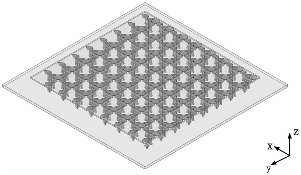
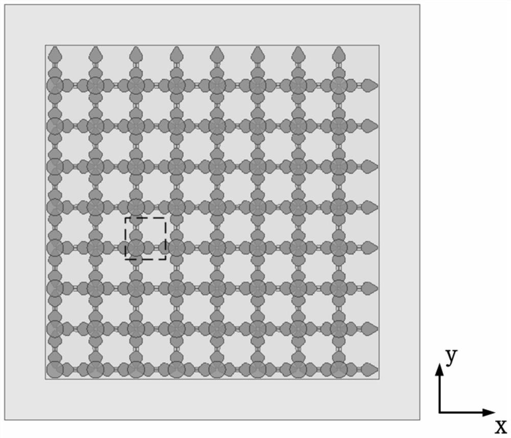
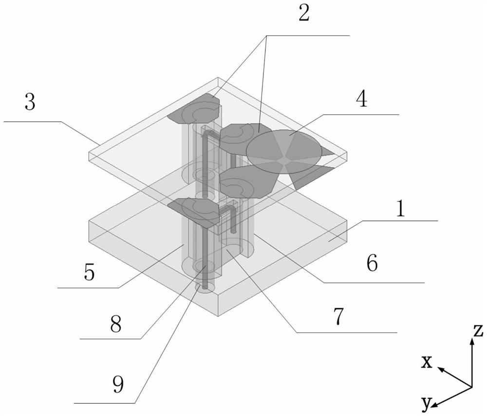
[0027] like figure 1 and 2 As shown, taking the small area array of 8×8 antenna units as an example, the units are periodically arranged on the reflector 1 according to a rectangular grid. In order to reduce the backward radiation, each side of the reflector 1 is larger than the radiation aperture composed of 8×8 antenna elements by one element spacing. The antenna elements such as image 3 and Figure 4 shown. An antenna unit of the array antenna includes two identical and orthogonal dipoles 2, a dielectric plate 3, a coupling patch 4 and a feeding device; wherein, t...


PUM

PropertyMeasurementUnit
thicknessaaaaaaaaaa

Abstract

In the prior art, the distance between tightly-coupled antenna units is always relatively compact, and due to the limited size, the design difficulty of a rear-end assembly is increased, the number of channels is increased, and the system cost is increased. The invention provides a thin-type dual-polarization ultra-wideband wide-angle scanning array antenna. The thin-type dual-polarization ultra-wideband wide-angle scanning array antenna comprises a reflecting plate and a plurality of antenna units arranged on the upper surface of the reflecting plate, each antenna unit comprises two orthogonal planar dipoles, a coupling patch, a dielectric plate and a feed device; wherein the coupling patch is positioned above the intersection of the dipoles and is used for enhancing the coupling capacitance between the units so as to expand the bandwidth; the feed device comprises two independent outer conductors, an insulator and an inner conductor, provides an ultra wide band signal for the antenna and inhibits standing wave bad resonance under large unit spacing. According to the array antenna, the dual-polarization ultra-wideband wide-angle scanning electrical performance can be achieved, integration conformality is facilitated due to the thin and planarization characteristics, the system cost can be effectively reduced due to the large unit spacing, and the array antenna is suitable for a multifunctional radar system.

Description

technical field [0001] The invention belongs to the technical field of microwave antennas, and in particular relates to a thin dual-polarized ultra-wide bandwidth angular scanning array antenna. Background technique [0002] Faced with the rapidly growing demand for high data rate transmission in communication systems and increasingly complex radar detection and imaging applications, modern radio subsystems increasingly require phased array antennas to be more integrated and multifunctional, using single or It is the future development trend of phased array antennas that very few arrays complete the transmission and reception of signals covering multi-polarized wide frequency bands. In addition to the electrical performance requirements of multi-polarization and ultra-wideband, many carrier platforms often also hope that the phased array antenna can achieve a planar structure and have a low profile height, so as to effectively reduce the protruding or exposed part of the pla...

Claims


Application Information

Patent Timeline
Patent Type & Authority Applications(China)
IPC IPC(8): H01Q1/36H01Q1/38H01Q1/48H01Q1/50H01Q5/25H01Q21/00
CPCH01Q5/25H01Q21/00H01Q1/36H01Q1/48H01Q1/50H01Q1/38
Inventor 张航宇朱富国王力陈敏王侃刘英
Owner CHINA ELECTRONICS TECH GRP CORP NO 14 RES INST
Why Eureka
Try Eureka