

Magnetic sensor formed on semiconductor substrate
A magnetic sensor and semiconductor technology, applied in the field of magnetic sensors, can solve the problems of inability to detect external magnetic field Hext, high current consumption, lack of sensitivity, etc.
- Summary
- Abstract
- Description
- Claims
- Application Information
AI Technical Summary
Problems solved by technology
Method used
Image

Examples
Embodiment Construction
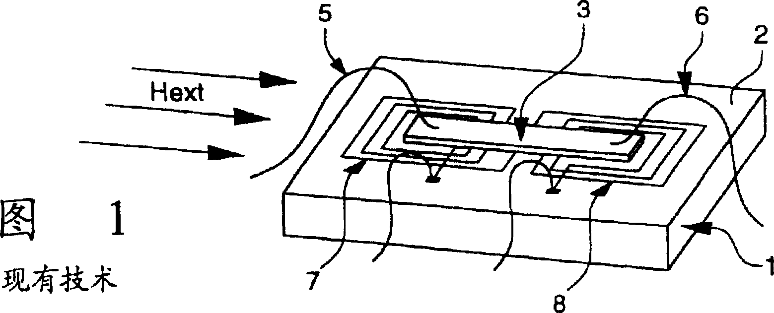
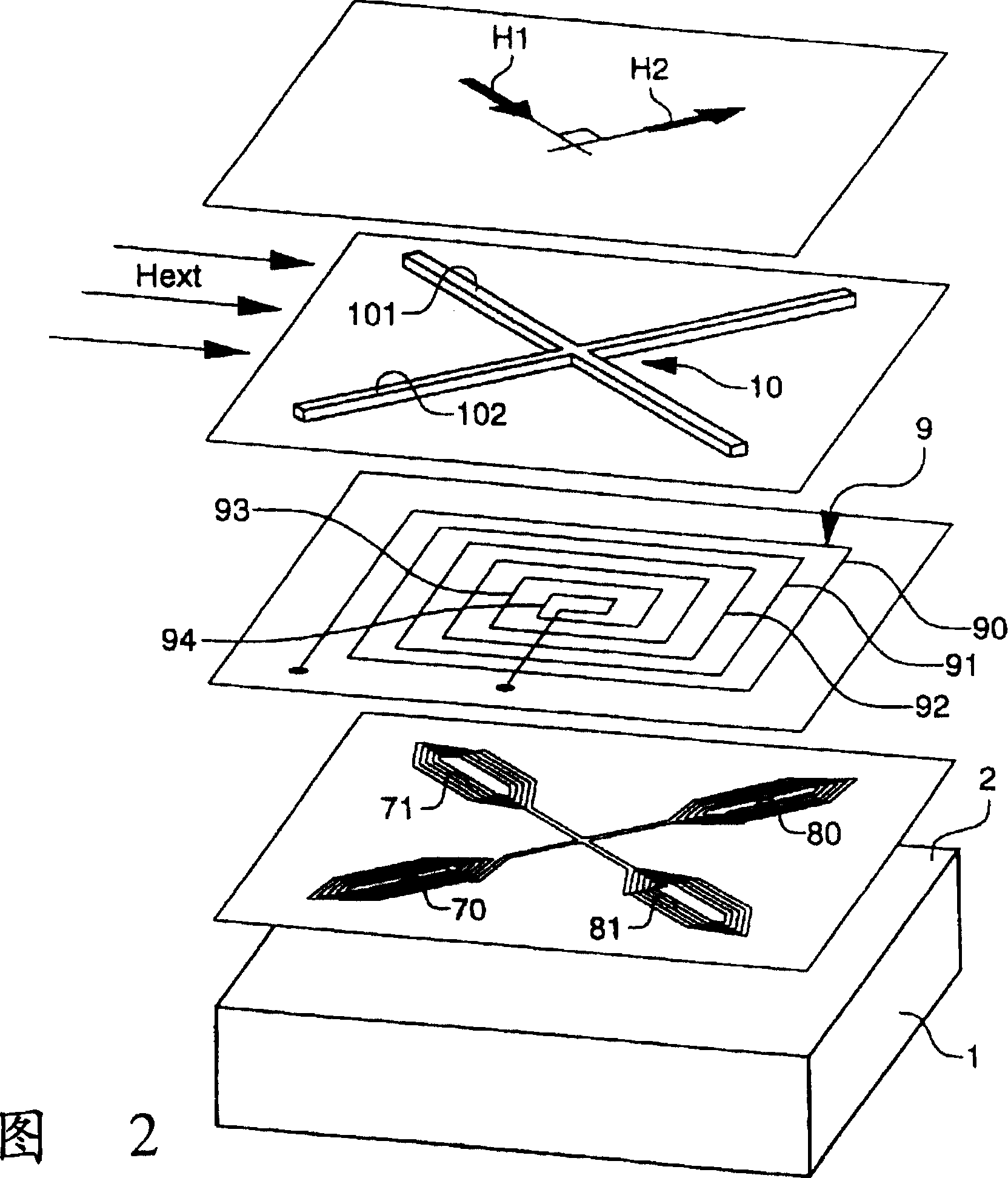
[0024] In FIG. 2, a parallelepiped-shaped substrate, similar to that of the prior art sensor in FIG. 1 described above, is designated by reference numeral 1. In FIG. This substrate comprises, made by CMOS integration on its large top surface 2, the electronic circuit combined with the magnetic sensor to make the complete magnetometer, the integrated electronic circuit not shown in the figure.
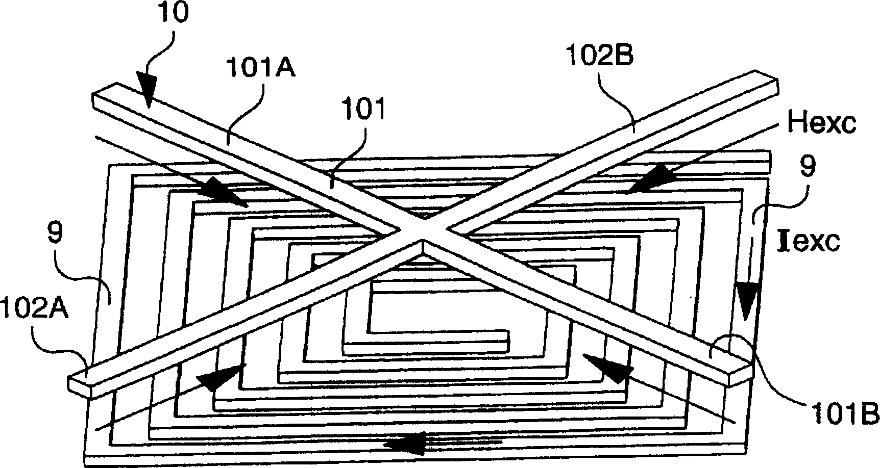
[0025] The sensor comprises a planar excitation coil 9 formed on the surface 2 of the substrate 1 , which coil 9 has a substantially square outer contour formed by an outer ring 90 . The other turns 91 to 94 of the field coil 9 are concentric with the outer turn 90, are also square and, as shown, are of decreasing size.
[0026] A ferromagnetic core 10 is usually fabricated on the field coil 9 by welding, said core being formed from an amorphous magnetic material, as in the case of the prior art device in FIG. 1, usually from a commercially available amorphous Crystalline ferromagnetic...
PUM
 Abstract
Description
Claims
Application Information