
Mass and heat recovery system for a fuel cell power plant

A power plant, fuel cell technology, applied in fuel cells, regenerative fuel cells, fuel cell additives, etc., can solve problems such as the complexity of self-sufficient water balance

Inactive Publication Date: 2004-07-28
UTC FUEL CELLS CORP
View PDF4 Cites 0 Cited by
  • Summary
  • Abstract
  • Description
  • Claims
  • Application Information

AI Technical Summary

Problems solved by technology

Humidifying the gas flow to stabilize the performance of the fuel processing element will further complicate maintaining a self-sufficient water balance for such fuel cell power plants when the working oxidant flow of the fuel processing element is supplied by ambient air
[0011] Accordingly, known fuel cell power plants and power plants employing ambient air as the cathode oxidant, or power plants employing ambient air to condense heat exchangers and / or fuel processing components, cannot be used due to their above-mentioned characteristics. Efficient water balance maximized and operating energy minimized

Method used


Image

  • Mass and heat recovery system for a fuel cell power plant
  • Mass and heat recovery system for a fuel cell power plant

Examples


Embodiment Construction

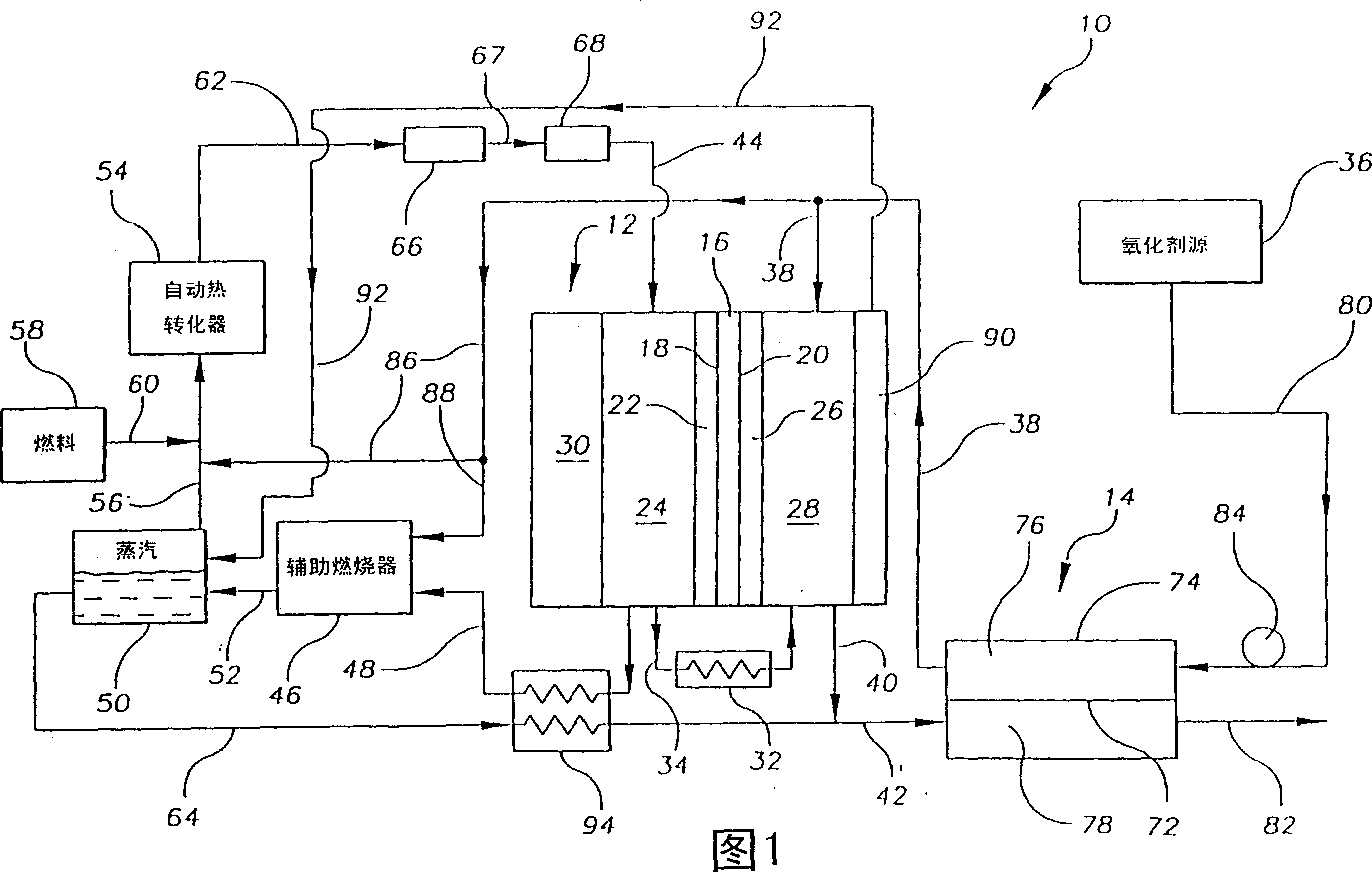
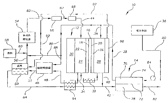
[0039] Referring to the accompanying drawings in detail, the material and heat recovery system of the fuel cell power plant of the present invention is shown in the figure, and is indicated by a reference number 10 . System 10 includes at least a fuel cell 12 and a direct mass and heat transfer device 14 . Fuel cell 12 includes an electrolyte 16, such as a proton exchange membrane ("PEM") or an acid or base electrolyte, having a first major surface 18 and an opposing second major surface 20; an anode electrode 22, supported by a porous anode support layer 24, and in intimate contact with the first major surface 18 of the electrolyte 16; and a cathode electrode 26, supported by a porous cathode support layer 28, and in intimate contact with the second major surface 20 of the electrolyte 16 touch. The anode and cathode porous support layers 24, 28 may be formed from porous or grooved graphite, carbon or metal plates. Fuel cell 12 may be combined with other substantially identi...


PUM


Abstract

A mass and heat recovery system for a fuel cell power plant includes at least one fuel cell for producing electrical energy, hydrocarbon fuel processing components for producing a hydrogen rich reducing fluid for the fuel cell, and a direct mass and heat transfer device for recovering mass and heat such as water vapor leaving the plant. The fuel processing components include an auxiliary burner that provides heat to generate steam and a reformer that receives the steam mixed with a hydrocarbon fuel along with a small amount of air and converts the mixture to a hydrogen rich stream appropriate for supplying hydrogen to the anode electrode. The direct mass and heat transfer device passes a process oxidant stream upstream of the plant in mass transfer relationship with a plant exhaust stream that includes both a cathode exhaust stream and an anode exhaust stream wherein the anode exhaust stream has first been burned in the auxiliary burner so that mass and heat such as water vapor in the plant exhaust stream transfer directly through a mass transfer medium of the device to the process oxidant stream entering the plant. The device includes a separator housing for supporting the transfer medium and for preventing bulk mixing of the streams. An exemplary transfer medium such as a liquid water portion of a water saturated polyflourosulfonic ionomer selectively sorbs a fluid substance consisting of polar molecules such as water molecules from a fluid stream containing polar and non-polar molecules.

Description

technical field [0001] The present invention relates to fuel cell power plants suitable for use in transportation vehicles, portable power plants, or stationary power plants, and in particular to a fuel cell capable of recovering matter and heat (e.g., water vapor) exiting the power plant The power plant, which transfers matter and heat back to the power plant to enhance water balance and power plant energy efficiency. Background technique [0002] Fuel cell power plants are well known and are commonly used to generate electrical energy from reducing and oxidizing fluids to power electrical consumers, for example, on a spacecraft. In such power plants, a plurality of planar fuel cells are typically arranged in a stack surrounded by an electrically insulating frame structure that defines manifolds that direct the flow of reductant, oxidant, coolant and product fluids. Each individual cell typically includes an anode electrode and a cathode electrode separated by an electroly...

Claims


Application Information

Patent Timeline
IPC IPC(8): H01M8/10H01M8/04H01M8/06
CPCH01M8/04089H01M2300/0005H01M8/04119H01M2250/20Y02T90/32H01M8/0612H01M8/04022H01M2300/0082Y02E60/50H01M8/04029Y02T90/40H01M8/04H01M8/06
Inventor 托马斯·F·富勒保罗·R·马尔焦特莱斯利·L·范戴恩
Owner UTC FUEL CELLS CORP
Learn More