
Method for thermal producing ultrathick oil by cyclic steam stimulation and special apparatus thereof

A special device and ultra-heavy oil technology, applied in the direction of isolation device, production fluid, earthwork drilling and production, etc., can solve the problems of casing damage, heat loss of wellbore without protection casing, long operation time, etc., to avoid heat loss Stress concentration, good heat insulation effect, and improved production efficiency

Inactive Publication Date: 2004-12-01
SPECIAL OIL DEV ZHONGYOU LIAOHE OIL FIELD CORP
View PDF0 Cites 0 Cited by
  • Summary
  • Abstract
  • Description
  • Claims
  • Application Information

AI Technical Summary

Problems solved by technology

Therefore, part of the heat energy is lost, and the operation time is long, which will easily cause well washing and pollute the oil layer, increase the cleaning cost of the heat insulation pipe and oil pipe, and easily cause well site pollution; the general operating cost accounts for a high proportion of the cost per ton of oil The oil operation cost is generally around 100 yuan, accounting for 20% of the variable cost
[0004] 2. Poor sealing, serious casing damage
In the prior art, the packer sealing technology is adopted in the ultra-heavy oil production device. During steam injection, the packer seals off the annular space of the oil casing through thermal expansion, and a very large The temperature difference will cause the stress concentration at the card seal, which will easily damage the casing
Excessive expansion of the packer may also easily cause the packer to be stuck, and the pipe string cannot be lifted, resulting in oil well overhaul
In addition, due to the poor sealing effect of the thermal recovery packer, the closed casing steam injection method cannot protect the casing and reduce the heat loss of the wellbore.
[0005] 3. Large heat loss and high energy consumption during oil recovery

Method used


Image

  • Method for thermal producing ultrathick oil by cyclic steam stimulation and special apparatus thereof
  • Method for thermal producing ultrathick oil by cyclic steam stimulation and special apparatus thereof
  • Method for thermal producing ultrathick oil by cyclic steam stimulation and special apparatus thereof

Examples


Embodiment

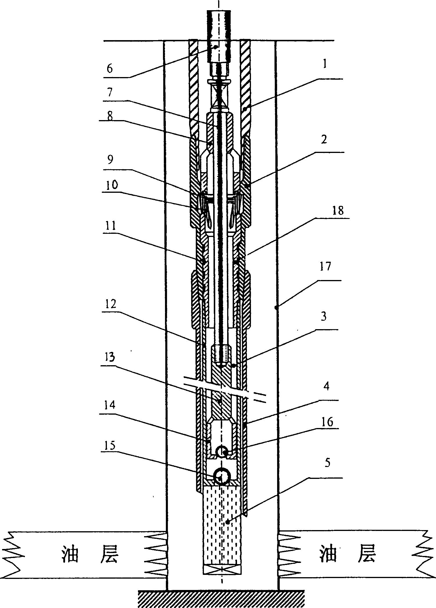
[0030] Such as figure 2 As shown, the working method of the present invention operates according to the following steps: 1) Lower the pipe string for steam injection; 2) Fill the annular cavity of the casing and the heat preservation tubing with high-pressure nitrogen, and perform steam injection according to the steam injection quantity, and the steam injection is completed Simmer the well and blow out; 3) Lower the sucker rod with sand control screen and rod pump, and then lower the cable in the hollow sucker rod to heat the oil; 4) Lift the sucker rod and inject steam after the end of oil production. Go back to step 2);

[0031] Such as image 3 As shown, the special device for the method of the present invention is placed in the casing 17, and the heat preservation tubing and the sucker rod constitute an integrated pipe string that integrates steam injection, oil production, heat preservation, sand washing and sand control. The heat preservation tubing 1 has a two-layer struct...


PUM


Abstract

The huff and puff thermal production method of high-viscosity crude includes the following steps: 1). lowering heat-insulating oil pipe, charging high-pressure nitrogen gas into the ring cavity between casing pipe and heat-insulating oil pipe, injecting steam, closing well and jetting; 2). lowering sucker-rod string and oil-production; 3). after oil production, taking out sucket-rod string, injecting steam and repeating the above-mentioned steps 2. Its special-purpose equipment includes an integrated pipe column formed from heat-insulating oil pipe and sucker-red string, said heat-insulating oil pipe possesses internal and external two-layer structure, between the heat-insualting oil pipe and casing pipe a ring cavity is formed, the sucker-rod string is a hollow suck-rod, its lower end is equipped with solid sucker-rod, rod pum and sand control screen structure.

Description

Technical field [0001] The invention relates to a super-heavy oil thermal recovery technology, in particular to a steam stimulation method and a special device for thermally recovering super heavy oil. Background technique [0002] In the prior art, there are many methods for the extraction of ultra-heavy oil. The main methods are steam injection with vacuum insulated pipes, medium frequency electric heating over pumps, and ground coal-fired (or gas dual-use) furnace insulation as the core steam huff and puff thermal recovery. In the process, the two production processes of steam injection and oil production use two casing strings respectively. Specifically, the steam injection uses insulated pipes, packers, and telescopic tubing strings, and oil production uses ordinary tubing strings and electric heating hollow rod strings. The main problems are: [0003] 1. Super heavy oil has a short huff and puff cycle and frequent operations. Generally, the super heavy oil throughput cycle ...

Claims


Application Information

Patent Timeline
Patent Type & Authority Patents(China)
IPC IPC(8): E21B17/18E21B36/04E21B43/24
Inventor 刘福余余五星郑南方薛海晖林军耿殿奇
Owner SPECIAL OIL DEV ZHONGYOU LIAOHE OIL FIELD CORP
Learn More