
Operational amplifying circuit, driving circuit and driving method

An operational amplifier circuit and operational amplifier technology, applied in the direction of amplifier combination, improved amplifier to improve efficiency, multiple input and output pulse circuits, etc., can solve the problems of large charge and discharge of liquid crystal display screen, and cannot achieve low power consumption, etc. Achieve the effect of low power consumption

Inactive Publication Date: 2005-01-05
SEIKO EPSON CORP
View PDF1 Cites 0 Cited by
  • Summary
  • Abstract
  • Description
  • Claims
  • Application Information

AI Technical Summary

Problems solved by technology

Therefore, there is a problem that low power consumption cannot be achieved until now due to the large charge and discharge of the liquid crystal display and the operating current of the operational amplifier circuit that drives the analog voltage.

Method used


Image

  • Operational amplifying circuit, driving circuit and driving method
  • Operational amplifying circuit, driving circuit and driving method
  • Operational amplifying circuit, driving circuit and driving method

Examples


Embodiment Construction

[0050] Hereinafter, this embodiment will be described in detail with reference to the drawings.

[0051] The present embodiment described below does not limit the content of the present invention described in the claims. In addition, not all the structures described in this embodiment are essential as the solution means of the present invention.

[0052] 1. Liquid crystal device

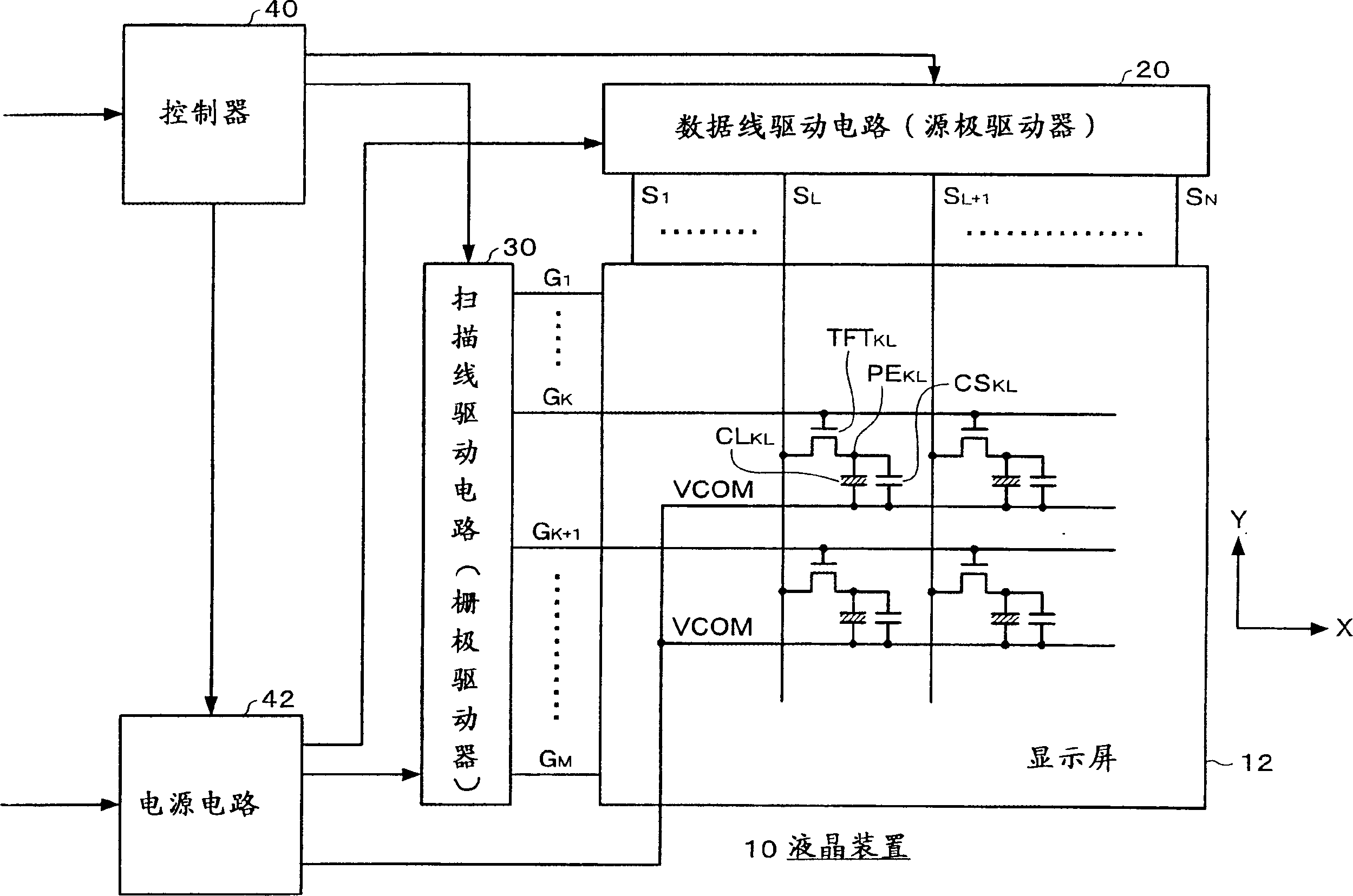
[0053] figure 1 An example of a block diagram of a liquid crystal device to which the operational amplifier circuit of this embodiment is applied is shown.

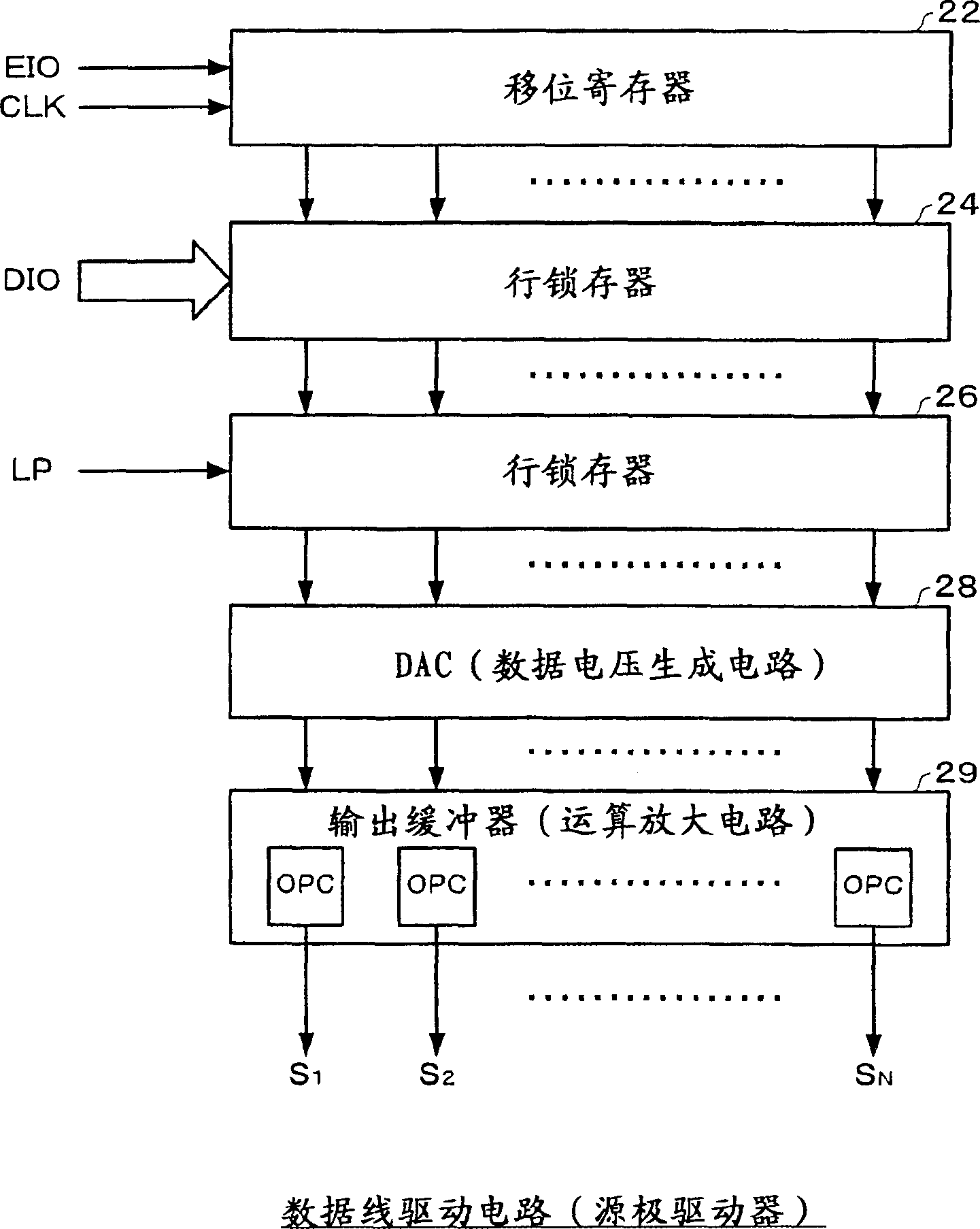
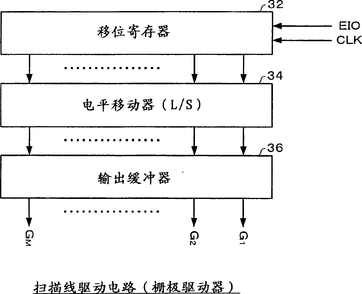
[0054] The liquid crystal device 10 (in a broad sense, a display device) includes a display screen 12 (in a narrow sense, an LCD (Liquid Crystal Display, liquid crystal display) screen), a data line driving circuit 20 (in a narrow sense, a source driver), and a scanning line driving circuit 30. (a gate driver in a narrow sense), a controller 40 , and a power supply circuit 42 . The liquid crystal device 10 does not necessarily include all of...


PUM


Abstract

An output of an operational amplifier circuit is set to the high impedance state in a given period including a transition between a period T1 (positive polarity) in which a voltage level of a counter electrode VCOM becomes VC1 and a period T2 (negative polarity) in which VCOM becomes VC2. In the period T1, data line is driven by a P-type operational amplifier OP1 having a P-type driving transistor, while in the period T2, the data line is driven by an N-type operational amplifier OP2 having an N-type driving transistor. By positively using a parasitic capacitance between the counter electrode and the data line, the voltage level of the data line is changed before driving. The excess charge is returned to the power source side by clamping the output of the operational amplifier circuit to a voltage range equal to or wider than a voltage range of power sources VDD and VSS. The voltage range of power sources VDD' and VSS' of a clamp circuit are set to be narrower than that of the power sources VDD and VSS of the operational amplifier circuit.

Description

technical field [0001] The invention relates to an operational amplifier circuit, a drive circuit, and a drive method. Background technique [0002] Conventionally, as liquid crystal displays (electro-optic devices) used in electronic devices such as mobile phones, simple matrix liquid crystal displays and active matrix devices using switching elements such as thin film transistors (Thin Film Transistor: hereinafter referred to as TFT) are known. way of the LCD screen. [0003] Compared with the active matrix method, the simple matrix method has the advantage of being easy to reduce power consumption, but has the disadvantage of being difficult to realize multicolor and animation display. There is, for example, a prior art disclosed in Japanese Patent Application Laid-Open No. Hei 7-98577 as a technology for reducing power consumption in such a simple matrix system. [0004] On the other hand, the active matrix method has the advantage of being suita...

Claims


Application Information

Patent Timeline
IPC IPC(8): G09G3/20G09G3/36H03F1/02H03F3/68H03K5/08H03K5/24
CPCH03K5/2481G09G3/3688H03K5/086G09G2330/021G09G3/3655G09G3/2011G09G3/3614G09G3/36
Inventor 石山久展
Owner SEIKO EPSON CORP
Learn More