Negative dispersion monomode optical fibre
A single-mode fiber, negative dispersion technology, used in optics, light guides, optical components, etc., can solve the problem of fiber dispersion characteristics excluding L-band and other issues
- Summary
- Abstract
- Description
- Claims
- Application Information
AI Technical Summary
Problems solved by technology
Method used
Image
Examples
Embodiment 1
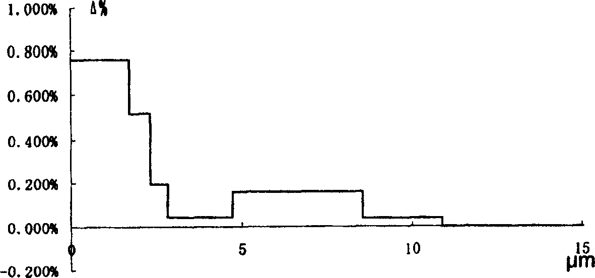
[0068] image 3 Shown is the distribution of the refractive index profile of the fiber in Example 1 of the negative dispersion fiber of the present invention.
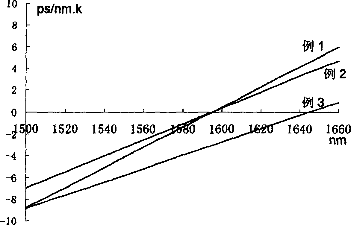
[0069] figure 2 The slanted line in Example 1 is the dispersion characteristic of Example 1 of the negative dispersion fiber of the present invention.
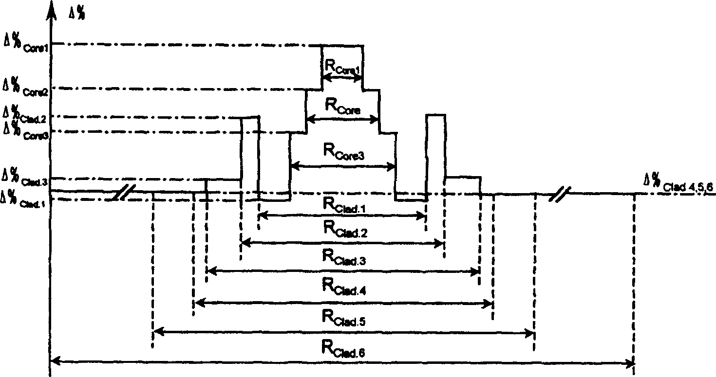
[0070] The fiber is a single-mode fiber, which has three core layers Core1, Core2, Core3 and six cladding layers Clad.1, Clad.2, Clad.3, Clad.4, Clad.5, Clad.6 ,in:
[0071] - First core layer Core1 with a relative refractive index difference Δ% Core1 approximately 0.760% of its diameter R Core1 About 3.4 μm.
[0072] - Second core layer Core2 with relative index difference Δ% Core2 approximately 0.520% of its diameter R Core2 About 4.6 μm.
[0073] - Third core layer Core3 with relative index difference Δ% Core3 approximately 0.190% of its diameter R Core3 About 5.6 μm.
[0074] - First cladding layer Clad.1 with relative refractive index difference Δ% Cl...
- Embodiment 2
[0100] Figure 4 Shown is the distribution of the refractive index profile of the fiber in Example 2 of the negative dispersion fiber of the present invention.
[0101] figure 2 The slanted line in Example 2 is the dispersion characteristic of Example 2 of the negative dispersion fiber of the present invention.
[0102] The fiber is a single-mode fiber, which has three core layers Core1, Core2, Core3 and six cladding layers Clad.1, Clad.2, Clad.3, Clad.4, Clad.5, Clad.6 ,in:
[0103] - First core layer Core1 with a relative refractive index difference Δ% core1 is about 0.758% of its diameter R core1 About 4.0 μm.
[0104] - Second core layer Core2 with relative index difference Δ% core2 is about 0.519% of its diameter R core2 About 5.3 μm.
[0105] - Third core layer Core3 with relative index difference Δ% core3 approximately 0.190% of its diameter R core3 About 6.2 μm.
[0106] - First cladding layer Clad.1 with relative refractive index difference Δ% Clad.1 is a...
Embodiment 2
[0113] The optical fiber of Embodiment 2 of the invention has the following characteristics:
[0114] - Dispersion characteristics
[0115] 1550nm dispersion coefficient: -3.4ps / nm.km
[0116] 1525nm to 1565nm dispersion coefficient range: -1.0ps / nm.km to -6.0ps / nm.km
[0117] 1550nm dispersion slope: 0.073ps / nm 2 .km
[0118] Zero dispersion wavelength: 1595nm
[0119] - Attenuation characteristics
[0120] 1550nm attenuation coefficient: 0.208dB / km
[0121] - Uncabled fiber cut-off wavelength λ c : 1300nm to 1400nm
[0122] -1550nm mode field diameter MFD: 8.2μm
[0123] -1550nm effective area A eff : 53μm 2
[0124] -Macrobending loss (75mm mandrel, 100 turns)
[0125] 1550nm: ≤0.01dB
[0126] - Hydrogen loss characteristics (1%H 2 Add 99% He, keep at 70°C for 16 hours)
[0127] 1530nm: ≤0.001dB / km
[0128] - PMD coefficient of uncabled fiber: ≤0.035ps / km 1 / 2
[0129] The single-mode fiber described in Embodiment 2 of the invention has a negative dispersio...
PUM
| Property | Measurement | Unit |
|---|---|---|
| diameter | aaaaa | aaaaa |
| diameter | aaaaa | aaaaa |
| diameter | aaaaa | aaaaa |
Abstract
Description
Claims
Application Information
 - R&D
- Intellectual Property
- Life Sciences
- Materials
- Tech Scout
- Unparalleled Data Quality
- Higher Quality Content
- 60% Fewer Hallucinations
Browse by: Latest US Patents, China's latest patents, Technical Efficacy Thesaurus, Application Domain, Technology Topic, Popular Technical Reports.
© 2025 PatSnap. All rights reserved.Legal|Privacy policy|Modern Slavery Act Transparency Statement|Sitemap|About US| Contact US: help@patsnap.com


