Single-phase electronic power-saving device

A power saving and electronic technology, applied in the electronic field, can solve the problems of electricity loss, electricity waste, aggravation, etc., and achieve the effect of reducing line temperature, protecting electrical equipment, and reducing electricity waste

Inactive Publication Date: 2005-06-22
SHENZHEN JIAYILAI IND
View PDF0 Cites 0 Cited by
  • Summary
  • Abstract
  • Description
  • Claims
  • Application Information

AI Technical Summary

Problems solved by technology

In fact, in the current power consumption system, no power-saving measures are taken, and a large amount of power is actually wasted
What is even more worrying is that in the process of using electricity, a large amount of electricity is lost, and the pollution to the environment is also increasing. At present, 70% of my country's electricity depends on coal, and every kilowatt-hour of electricity produced must rely on us. With the atmospheric emission of 1100 grams of carbon dioxide, 9 grams of sulfur dioxide and 4.4 grams of nitrogen oxides, a single-phase electronic power saver that consumers can afford can be developed, which can not only save electricity and money, but also protect electrical equipment and protect environment, the popularization and popularization of safe single-phase electronic power savers is also an urgent development direction for the power saving industry

Method used


Image

  • Single-phase electronic power-saving device
  • Single-phase electronic power-saving device
  • Single-phase electronic power-saving device

Examples


Embodiment Construction

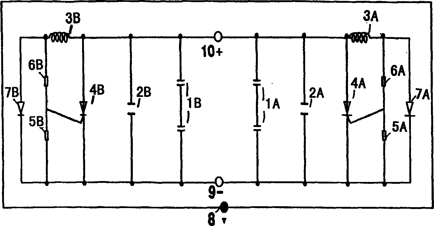
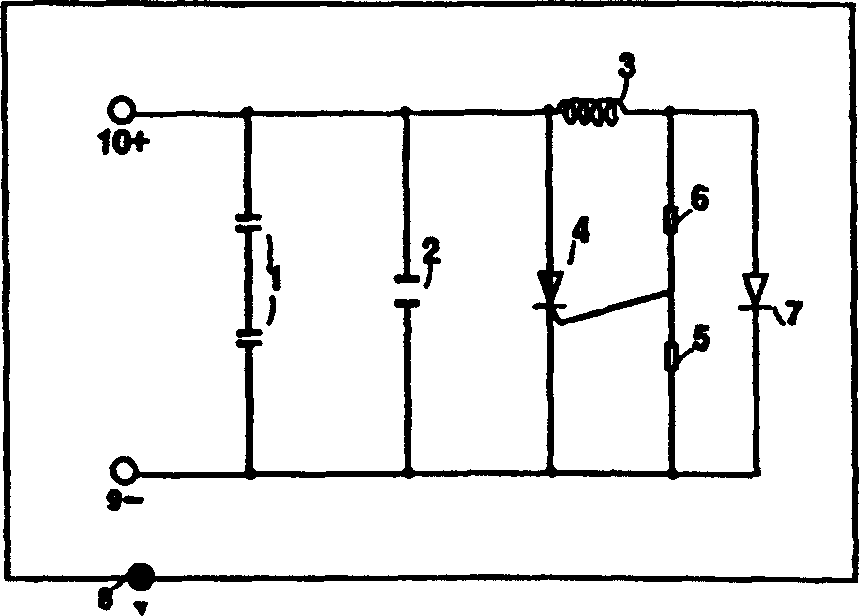
[0019] Please refer to figure 1 , figure 1 A circuit structure of the specific scheme of the large power saver of the present invention is given. There are two groups of power saving devices in the large power saver, which are respectively a group of strong power saving devices and a group of weak power saving devices.

[0020] Strong power saving device has two ceramic capacitors 1A, safety capacitor 2A, inductor 3A, thyristor 4A, first resistor 5A, second resistor 6A, indicator light 7A, ground wire structure 8, neutral wire 9, live wire 10 ;Two ceramic capacitors 1A are connected in series and connected between live wire 10 and neutral wire 9, safety capacitor 2A is connected in parallel with two ceramic capacitors 1A, one end of inductor 3A is connected to live wire 10, and the other end of inductor 3A is connected in series The second resistor 6A and the first resistor 5A are then connected to the zero line 9, the anode of the thyristor 4A is connected between the safety...


PUM


Abstract

A single-phase electronic power saver, which is composed of a power saving device. The structure of the power saving device is: two ceramic capacitors (1) are connected in series and connected between the live wire (10) and the neutral wire (9). The capacitor (2) is connected in parallel with two ceramic capacitors (1), one end of the inductor (3) is connected to the live wire (10), and the other end of the inductor (3) is connected in series with the second resistor (6) and the first resistor (5). Connect with the zero line (9), the anode of the thyristor (4) is connected between the safety capacitor (2) and the inductor (3), the cathode of the thyristor (4) is connected between the safety capacitor (2) and the first Between the first resistor (5), the control pole of the thyristor (4) is connected between the first resistor (5) and the second resistor (6), and one end of the indicator light (7) is connected between the inductor (3) and the second resistor (6). Between the two resistors (6), the other end of the indicator light (7) is connected between the first resistor (5) and the silicon controlled rectifier (4); the single-phase electronic power saver is installed on a single-phase power supply to provide stable power supply voltage, filter transient surges, balance line current, prolong the service life of equipment, have multiple functions such as safety and power saving, and have a certain power saving effect for single-phase power consumption systems.

Description

technical field [0001] The present invention relates to an electronic field, specifically to an electronic product, and more specifically to a single-phase electronic power saver. Background technique [0002] The current single-phase power savers on the market are power savers for a single electrical appliance, such as power savers for air conditioners, power savers for electric water tanks, energy-saving lamps, and lighting power savers. Single-phase power savers, such as multi-functional and comprehensive power savers suitable for indoor, home, commercial, electrical, and industrial use, are rare in the market. Even if there are, they are difficult to accept because of their complex structure and high cost. [0003] It is a new trend of green environmental protection to adopt scientific energy-saving methods to reduce electricity waste and protect electrical equipment. In our country, the cost of electricity for some products is higher than that of developed countries, a...

Claims


Application Information

Patent Timeline
Patent Type & Authority Patents(China)
IPC IPC(8): H02J3/00H02J3/18
CPCY02E40/30
Inventor 张嘉义
Owner SHENZHEN JIAYILAI IND
Why Eureka
Try Eureka