Method for controlling transverse crystal orientation of metal monocrystal

A technology of crystal orientation and control method, which is applied in the direction of crystal growth, single crystal growth, chemical instruments and methods, etc., can solve the problems of lateral orientation that few people discuss, and achieve the effect of simple method and easy operation

Inactive Publication Date: 2005-07-06
INST OF METAL RESEARCH - CHINESE ACAD OF SCI
View PDF0 Cites 2 Cited by
  • Summary
  • Abstract
  • Description
  • Claims
  • Application Information

AI Technical Summary

Problems solved by technology

However, whether the crystal growth can be controlled by a crystal generator to control its lateral orientation is rarely discussed.

Method used


Image

  • Method for controlling transverse crystal orientation of metal monocrystal
  • Method for controlling transverse crystal orientation of metal monocrystal
  • Method for controlling transverse crystal orientation of metal monocrystal

Examples


Embodiment 1

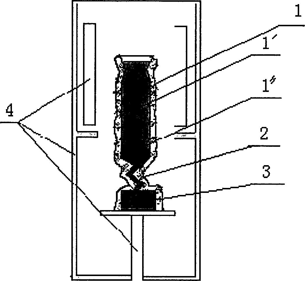
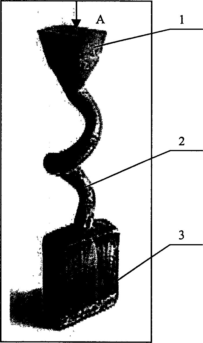
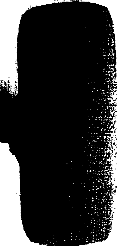
[0022] Such as Figure 1b As shown, the TMS64 single crystal superalloy sample is used as the single crystal casting 1, the cross section of the crystal lifter 3 is rectangular, 30mm long and 8mm wide, and the crystal lifter 3 is 30mm high to introduce an additional directional transverse thermal field; the crystal selector 2 is a spiral The structure adopts investment precision casting ceramic shell technology, grows single crystal in ZGD-2 gradient furnace, melt temperature is 1600 ℃, and pulling speed is 3mm / min; the result of single crystal lateral crystal orientation during crystal growth is as follows: Figure 1c As shown, the single crystal sample takes a rectangular cross-section, the long axis direction is the predetermined direction of the transverse [001] orientation, and a single crystal with the transverse orientation consistent with the predetermined direction is obtained, and the deviation is less than 15°;

[0023] In the figure, 1' is liquid metal, and 1" is c...

Embodiment 2

[0032] Difference with embodiment 1 is: the inventive method is applied to DD8 single crystal superalloy, and single crystal sample section is circular, and crystal riser 3 section is still rectangular, long 20mm, wide 4mm, its height 40mm; But melting The body temperature was 1550°C, and the pulling speed was 4mm / min; the basic process was the same as in Example 1, and the transverse [001] orientation of the obtained single crystal sample was consistent with the long axis direction of the crystal riser 3, and the deviation was less than 15°.

Embodiment 3

[0034] Difference with embodiment 1 is: the inventive method is applied to DD98 single crystal superalloy, and its cross-section is circular; Crystal riser 3 cross-sections are rectangular, long 50mm, wide 20mm, its height 50mm; Other and embodiment 1 Similarly, the transverse [001] orientation of the obtained single crystal sample is consistent with the long axis direction of the crystal riser 3, and the deviation is less than 15°.

[0035] The cross-section of the crystal riser 3 in the present invention can also be in a shape similar to a rectangle, such as one of polygonal, waist-shaped, square, etc., with a pair of relatively long, relatively parallel opposite sides as a principle.


PUM

PropertyMeasurementUnit
lengthaaaaaaaaaa
widthaaaaaaaaaa
heightaaaaaaaaaa

Abstract

The invention relates to the preparation technology of metal single crystal, in particular to a method for controlling the transverse crystal orientation of metal single crystal. In the single crystal furnace, a crystal selector and a crystal riser are provided, and the crystal selection method is used to grow single crystal castings; wherein: the crystal riser adopts a rectangular or quasi-rectangular cross-section with a pair of long, relatively parallel opposite sides , so as to introduce an additional directional transverse thermal field to control the transverse crystal orientation of the single crystal during the crystal growth process, use the conventional investment casting method to shape, pour liquid metal, and grow single crystal in the single crystal furnace. The invention can control the lateral crystal orientation of single crystal by introducing an additional directional transverse thermal field in the process of crystal growth and combining the characteristics of preferred orientation of crystal growth.

Description

technical field [0001] The invention relates to the preparation technology of metal single crystal, in particular to a method for controlling the transverse crystal orientation of metal single crystal. Background technique [0002] In the prior art, the main methods for preparing metal single crystals in gradient furnaces include the seed crystal method and the crystal selection method, wherein: the seed crystal method is essentially a method for epitaxy of liquid metal on a prefabricated single crystal mother sample (seed crystal). growth method, so theoretically the crystal orientation of a single crystal can be controlled, but the seed crystal method requires prefabricated seed crystals, and requires complex seed crystal orientation determination and seed crystal processing, the process is complex, and the process conditions are strict; the crystal selection method is Directly use the crystallization process of liquid metal itself, use a specific crystal selector to selec...

Claims


Application Information

Patent Timeline
Patent Type & Authority Patents(China)
IPC IPC(8): B22D27/04C30B11/00
Inventor 郑启孙晓峰侯桂臣管恒荣胡壮麒
Owner INST OF METAL RESEARCH - CHINESE ACAD OF SCI
Why Eureka
Try Eureka