

Pocket sized tester for high voltage vacuum tube
A vacuum tube and tester technology, applied in vacuum gauges using ionization effect, the manufacture of discharge tubes/lamps, electrical components, etc. Questions over 10,000 yuan
- Summary
- Abstract
- Description
- Claims
- Application Information
AI Technical Summary
Problems solved by technology
Method used
Image

Examples
Embodiment Construction
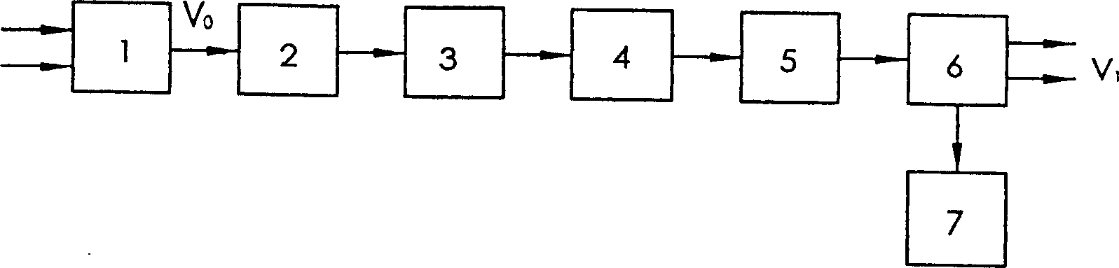
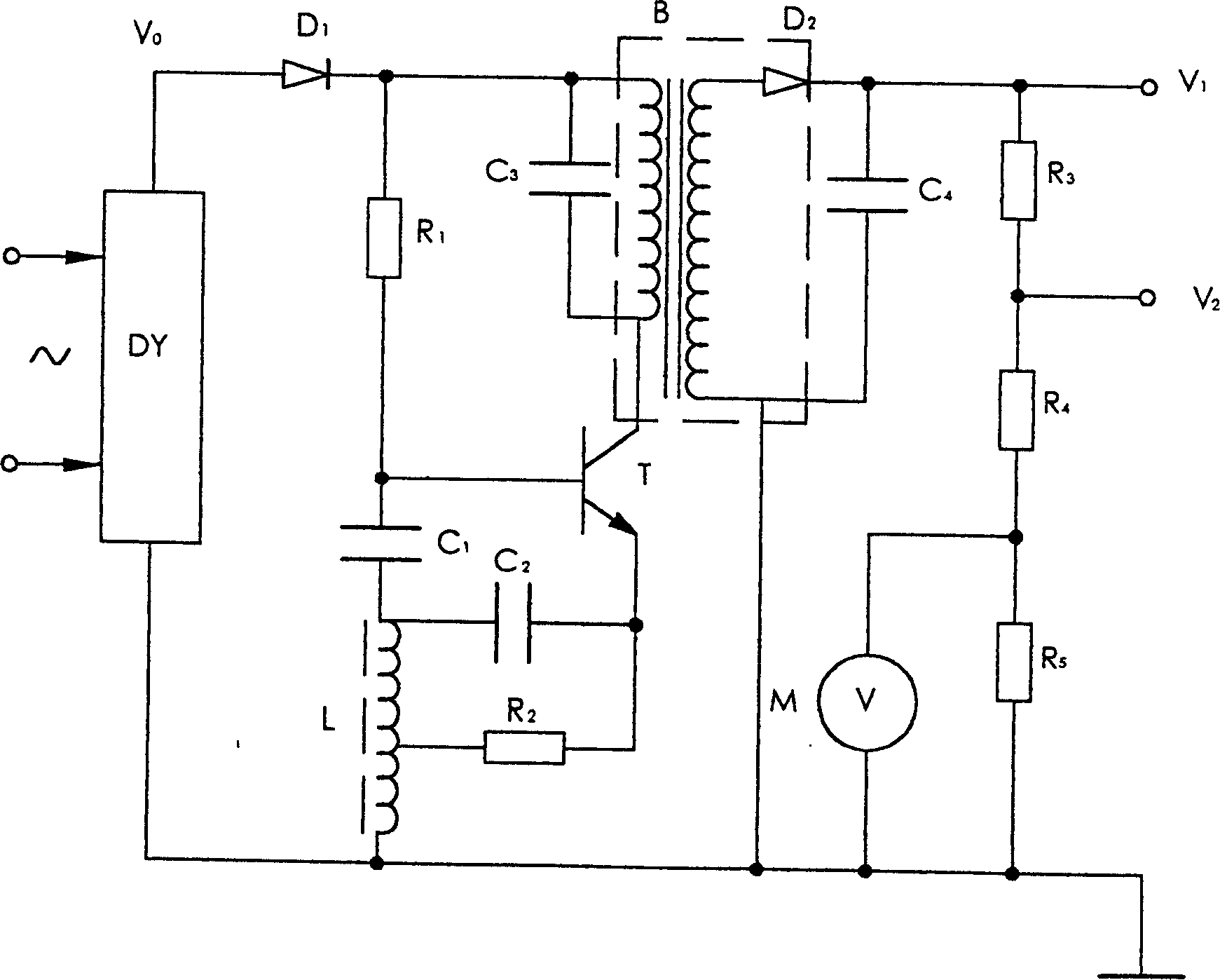
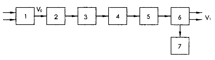
[0008] Such as figure 1 As shown, after the AC voltage is input, the DC voltage V is output through the regulated power supply 1 0 After passing through the isolation circuit 2, the pulse signal generation circuit 3 is sent to generate a high-voltage pulse with a steep rising edge. After passing through the boost rectification circuit 4 and the filter circuit 5, it is output to the output voltage division sampling circuit 6, and its sampling voltage output is connected to the display circuit 7. and display the DC high voltage V 1 (or DC voltage V 2 ).
[0009] The vacuum tube to be tested is connected to V 1 (or V 2 ) and the ground. After the power is turned on, the voltage indicated by the display voltmeter is the breakdown voltage value of the vacuum tube under test. The higher the breakdown voltage value, the higher the vacuum degree or the fewer conductive ions, the better the quality of the vacuum tube. When the measured breakdown voltage value is less than the s...
PUM
 Abstract
Description
Claims
Application Information