Photomultiplier and radiation sensor

A technology for photomultiplier tubes and a manufacturing method, which are applied in the directions of electron multiplier tubes, measuring devices, detailed information of electron multipliers, etc., and can solve problems such as obstacles to the use of photomultiplier tubes.

Inactive Publication Date: 2005-11-16
HAMAMATSU PHOTONICS KK
View PDF2 Cites 0 Cited by
  • Summary
  • Abstract
  • Description
  • Claims
  • Application Information

AI Technical Summary

Problems solved by technology

[0006] However, in a small photomultiplier tube using a metal side tube, flanges are formed on the side tube and the rod plate, and the hermetic container is formed by resistance welding. become an obstacle
In particular, when photomultiplier tubes are used in a gamma camera or the like, it is nec

Method used


Image

  • Photomultiplier and radiation sensor
  • Photomultiplier and radiation sensor
  • Photomultiplier and radiation sensor

Examples


Embodiment Construction

[0041] below, with Figure 1 The ideal embodiment of the photomultiplier tube of the present invention will be described in detail.

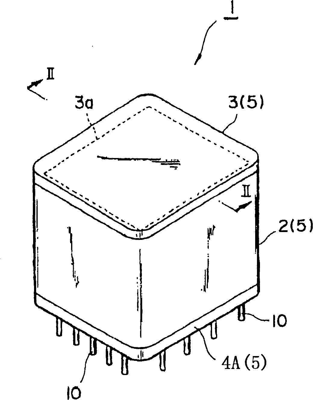
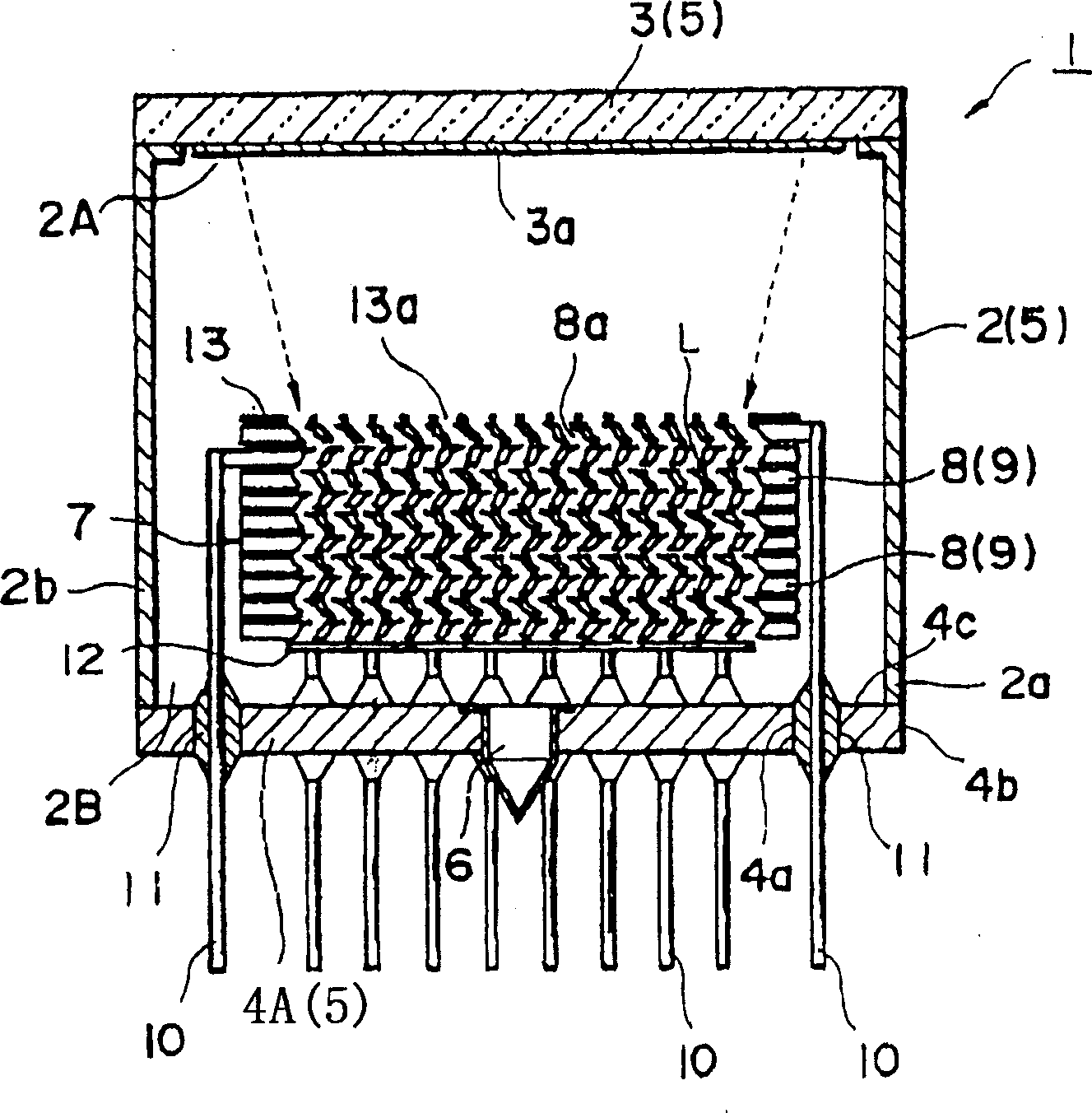
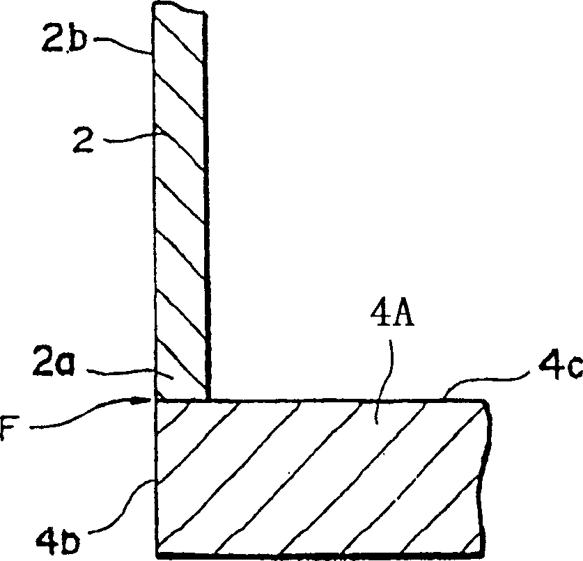
[0042] Fig. 1 is a perspective view showing a photomultiplier tube according to a first embodiment of the present invention, and Fig. 2 is a cross-sectional view of Fig. 1 . The photomultiplier tube 1 shown in these drawings has a side tube 2 made of metal (for example, made of Kovar (Kovar) iron-nickel-cobalt alloy or stainless steel) approximately in the shape of a square column, and the opening on one side of the side tube 2 is A light-receiving panel 3 made of glass is welded and fixed on the end 2A. On the inner surface of the light-receiving panel 3, a photoelectric surface 3a for converting light into electrons is formed. The antimony deposited on the surface reacts to form. In addition, a lever plate 4A made of metal (for example, made of Kovar metal or stainless steel) is welded and fixed to the opening end 2B of the side pipe 2 . Thu...


PUM


Abstract

With the outer wall surface (2b) of a metal-made side tube (2) of a photomultiplier flush with the edge face (4b) of a stem plate (4), the side tube (2) is secured to the stem plate (4) by welding, and thereby there is no projection like a flange at the bottom of the photomultiplier (1), reducing the size of the photomultiplier. Therefore, though it is difficult to perform resistance welding, the outside dimensions of the photomultiplier (1) can be decreased, and multiple photomultipliers (1) can densely abut to one another in such a way that the side tubes (2) are put together even if the photomultipliers (2) are arranged when applied. Hence, high-density arrangement of photomultipliers (1) are realized by assembling metallic stem plate (4) and the side tube (2) by, for example, laser welding.

Description

technical field [0001] The present invention relates to a photomultiplier tube having a structure for detecting weak light incident on a light-receiving panel by electron multiplication and a method of manufacturing the same. More specifically, the present invention relates to a radiation detection device using the photomultiplier tube. Background technique [0002] Photomultiplier tubes are manufactured in various sizes according to the application. The existing photomultiplier tubes generally use glass to form a sealed container as a whole. In order to manufacture the photomultiplier tube of this kind of glass airtight container, the lower opening of the glass side pipe, which is approximately cylindrical in plan, is fitted with a rod in the shape of a flat disk. The contact part of the peripheral part is heated and melted so that the two are airtightly welded. Similarly, a transparent light-receiving panel is airtightly welded to the upper opening of the side pipe in the...

Claims


Application Information

Patent Timeline
IPC IPC(8): G01N23/04G01N23/08H01J43/04H01J43/28
CPCG01N2223/419G01N23/08H01J43/04H01J43/28G01N23/046G01N23/06
Inventor 久浩之渥美明下井英树冈田知幸伊藤益保
Owner HAMAMATSU PHOTONICS KK
Why Eureka
Try Eureka