Liquid cooling of mould for making glass utensils

A glassware and mold technology, applied in the field of mold cooling, can solve the problems of lack of thermal conductivity and thermal cycle cracking resistance

Inactive Publication Date: 2006-07-12
OWENS-BROCKWAY GLASS CONTAINER INC
View PDF3 Cites 0 Cited by
  • Summary
  • Abstract
  • Description
  • Claims
  • Application Information

AI Technical Summary

Problems solved by technology

However, standard austenitic high-nickel ductile iron does not have ideal thermal conductivity and thermal cycle cracking resistance

Method used


Image

  • Liquid cooling of mould for making glass utensils
  • Liquid cooling of mould for making glass utensils
  • Liquid cooling of mould for making glass utensils

Examples


Embodiment Construction

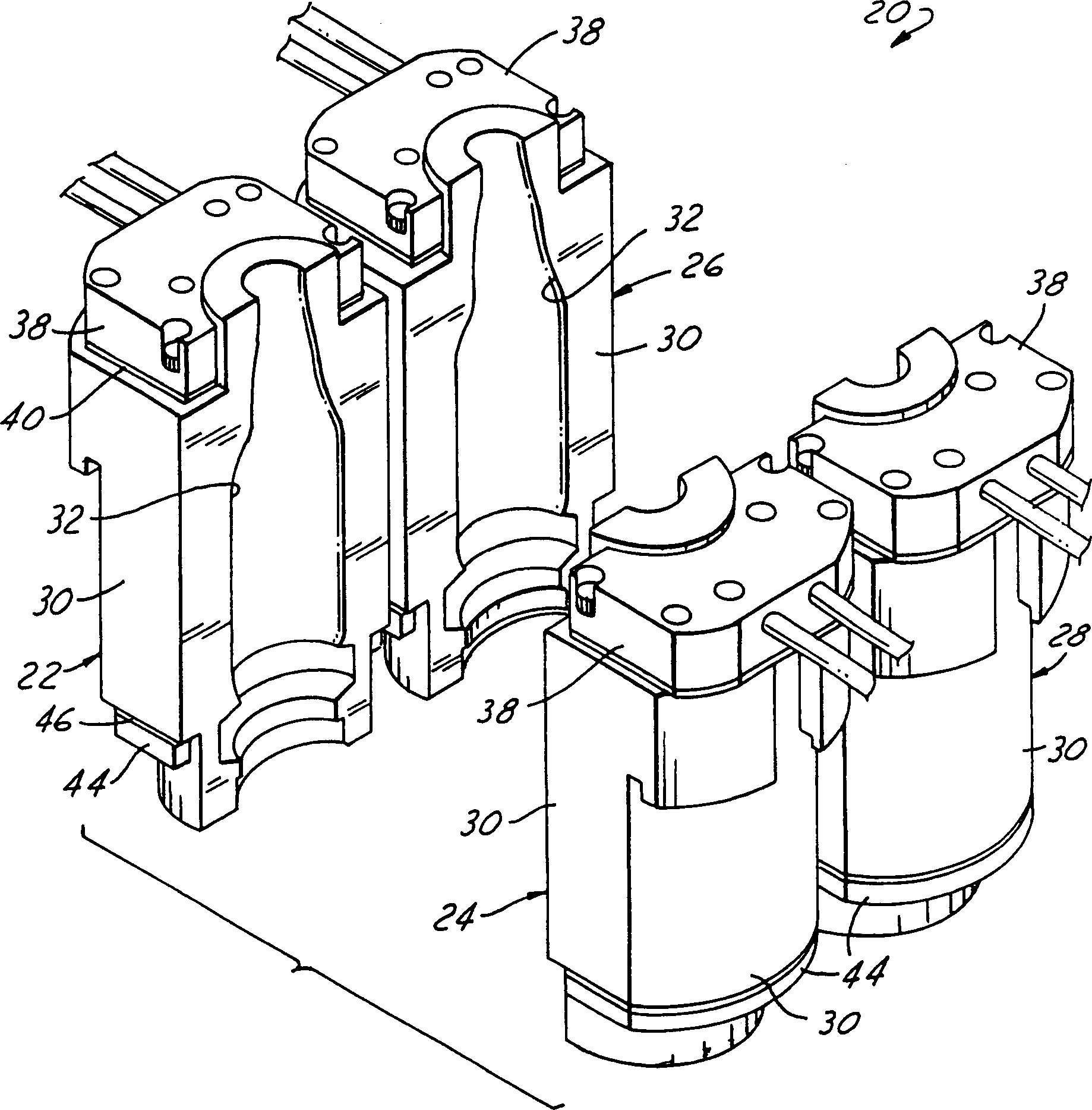
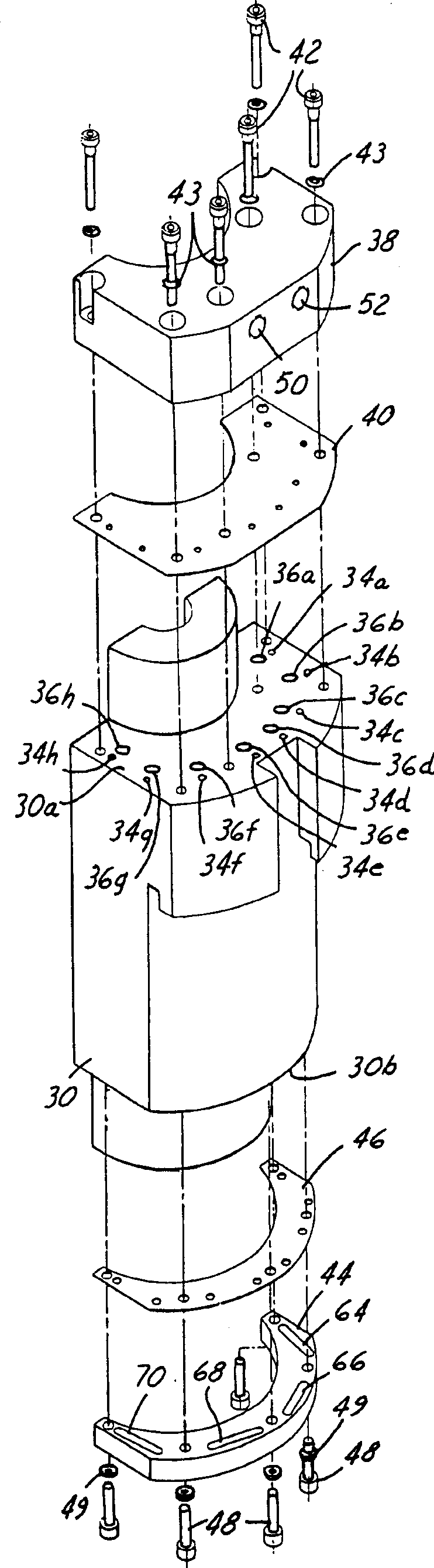
[0027] figure 1 Mold 20 is shown having a first pair of split molds 22, 24 and a second pair of split molds 26, 28, the illustrated modules 22-28 being blow molds for a dual zone bottle making machine (IS) . But the present invention is also equally applicable to the cooling of the blank mold ( Figure 16 ) combined application, and can be equally applied to other types of IS machine or rotary bottle making machine such as single machine, three machines and four machines. Each module 22-28 has a body and two opposing end plates. Combine below Figure 2-7 and 17 detailing module 22, it should be understood that module 26 is identical to module 22 and that modules 24, 28 are mirror images of module 22.

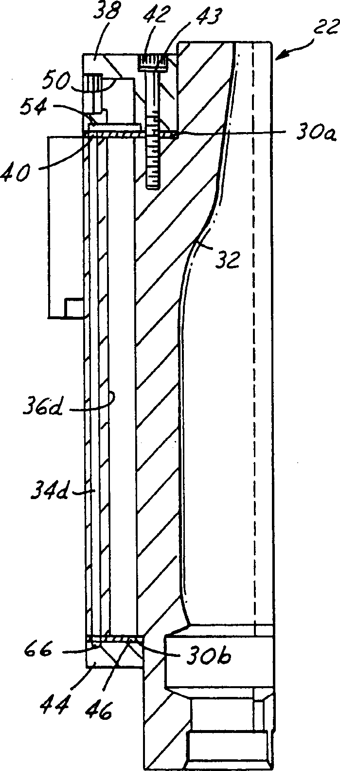
[0028]Mold 22 has a mold body 30 with a forming surface 32 in its central portion which, together with a corresponding forming surface of opposing mold 24, forms a surface for shaping molten glass during a pressing or blowing operation. Thus, the molten glass is in contact ...


PUM


Abstract

A glassware forming mold that includes a body (30 or 92) of heat conductive construction having a central portion with a forming surface (32 or 32a) for shaping molten glass and a peripheral portion spaced radially outwardly of the central portion. A plurality of coolant passages (34a to 34h, 54 to 70) extend in a spaced array through the peripheral portion of the mold body, and liquid coolant is directed through such passages for extracting heat from the body by conduction from the forming surface. A plurality of openings (36a to 36q) extend axially into the body radially between at least some of the liquid coolant passages and the forming surface for retarding heat transfer from the forming surface to liquid coolant in the passages.

Description

technical field [0001] The present invention relates to cooling of molds in glassware forming machines, and more particularly to liquid cooling of blank molds and / or blow molds in individual section bottle making machines. Background technique [0002] Glass container manufacturing techniques are now being realized by so-called zone bottle machines or IS machines. The machine has a plurality of separate or individual working sections, each with a plurality of chambers for converting one or more molten glass gobs or blanks into hollow glass containers and conveying the glass containers through the train. Machines for the operation of continuous stations, each of the above units containing: one or more blank films for forming the initial gob by blowing or pressing; one or more for transferring the glass blank to the Transfer arms within the blow mold for the final shape; grippers to remove the finished containers onto the heat barrier and a scraper mechanism to transfer the m...

Claims


Application Information

Patent Timeline
IPC IPC(8): C03B11/12C03B9/38C03B9/16C03B9/24C03B9/347
CPCC03B9/3875C03B9/3816
Inventor D·L·路易斯D·L·哈姆布利
Owner OWENS-BROCKWAY GLASS CONTAINER INC
Why Eureka
Try Eureka