Cracking furnace

A cracking furnace and furnace technology, used in cracking, non-catalytic thermal cracking, petroleum industry, etc., can solve the problems of poor uniformity of heating of the outlet pipe, large floor space, low space utilization, etc., and achieve uniformity of heat flux distribution. Good, easy to install and repair construction, not easy to coking effect

Inactive Publication Date: 2006-08-23
岳志
View PDF0 Cites 0 Cited by
  • Summary
  • Abstract
  • Description
  • Claims
  • Application Information

AI Technical Summary

Problems solved by technology

It can not only effectively solve the problems of the existing pyrolysis furnace, especially the single-row arrangement of furnace tubes in the radiant section, which occupy a large area and low space utilization rate, but also improve the furnace tubes of the existing furnace tubes arranged in two rows, especially the furnace tubes of the cracking furnace. The problem of poor circumferential heating uniformity of the outlet pipe

Method used


Image

  • Cracking furnace
  • Cracking furnace
  • Cracking furnace

Examples


Embodiment 1

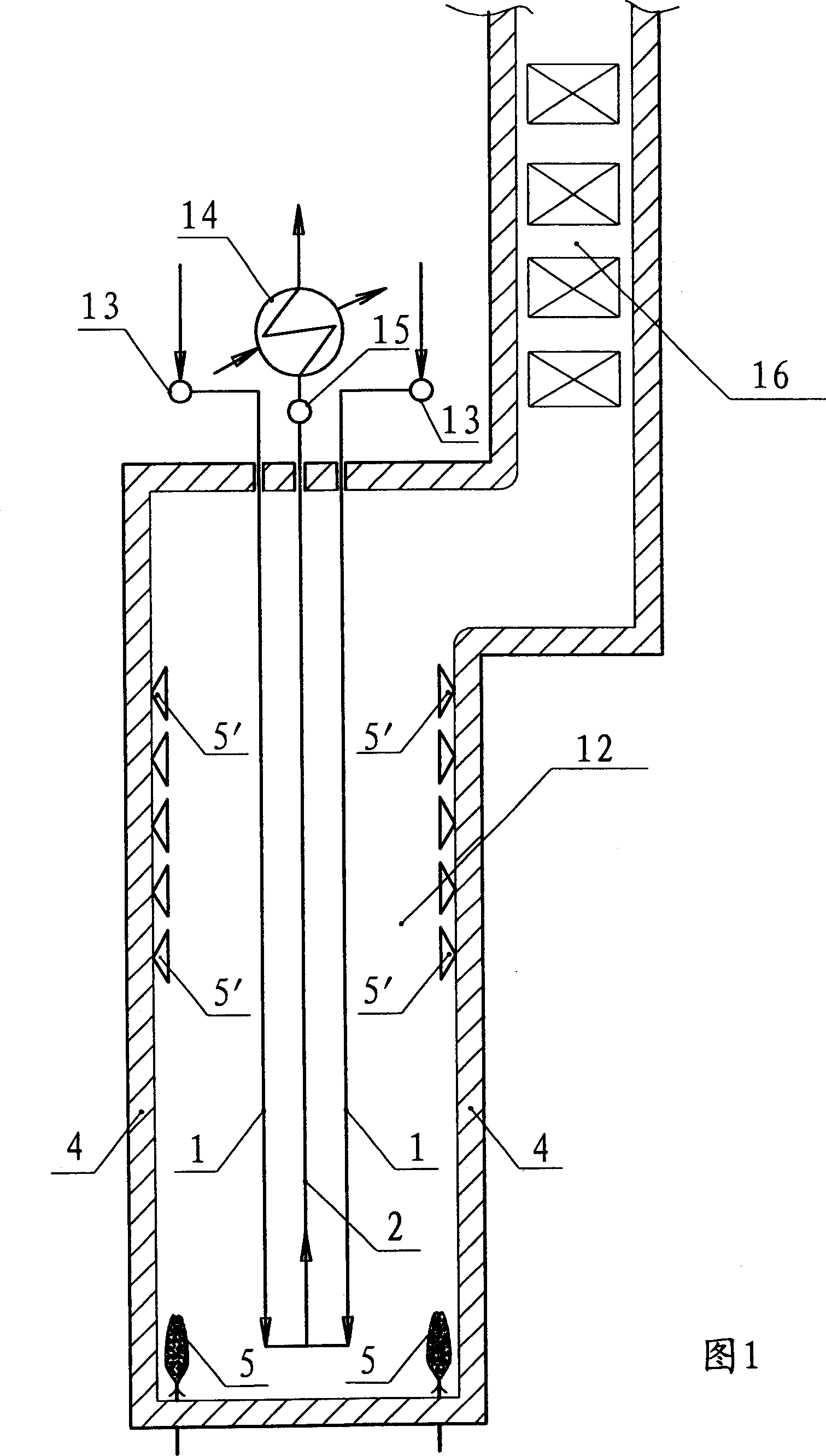
[0047] Referring to Fig. 1, be the simple structural representation of cracking furnace of the present invention, wherein, comprise: radiant section hearth 12; Be arranged in the burner 5,5 ' that is arranged in row in this fire hearth; Form a flame by at least a row of above-mentioned burner combustion Radiant surface 11, each furnace comprises at least two above-mentioned flame radiant surfaces 11; Radiant section reactor tube 1, 2 vertically arranged in the middle of above-mentioned every two flame radiant surfaces 11; An inlet manifold 13; a quenching heat exchanger 14 arranged outside the furnace, and a reaction tube outlet manifold 15 for connecting the outlets of the plurality of reaction tubes to the quenching heat exchanger 14.

[0048] Figure 2, Figure 3, Figure 4, Figure 5 The reference diagram of a preferred embodiment of the cracking furnace of the present invention is shown. In this example, the reaction tube is a two-pass reducing tube, and both the outlet tube...

Embodiment 2

[0051] Referring to Fig. 7, in this example, the reaction tube is still a two-pass reducing tube, and both the outlet and inlet pipes are single-channel. This is the same as the first embodiment. The difference from Embodiment 1 is: in this example, the outlet pipes 2 are arranged in two rows, and are symmetrically arranged on both sides of the horizontal centerline 6 of the two flame radiation surfaces, and the two rows deviate from the centerline 6 a certain distance. Considering the uniformity of heating, the distance should be as small as possible. Compared with the first embodiment, the distance between the adjacent outlet pipes 2 in this example can be larger, and they are not easy to collide with each other, and it can also bring certain convenience for installation and maintenance. Generally speaking, as long as the two rows of outlet pipes 2 are located between the two rows of inlet pipes 1, it can be said that although the heating uniformity of the outlet pipes may...

Embodiment 3

[0053] Figure 8 , Fig. 9, Fig. 10, are the simplified schematic diagrams of the third embodiment of the cracking furnace of the present invention. In this example, the reaction tube is still a two-pass reducing tube, but the inlet tube 1 is a double channel, and the outlet tube 2 is a single channel, that is, the process fluid passes through two parallel inlet tubes 1 and enters a connected outlet tube at the bottom of the furnace 2. Between a pair of radiation surfaces 11, the reaction tubes are arranged in three rows, the outlet tubes 2 are located in the middle row, and the inlet tubes 1 are divided into two rows, located on both sides of the row where the outlet tubes 2 are located. The reaction tubes can be arranged in three rows in a staggered manner, as shown in Figure 9, or they can be aligned (see Figure 11 ) or cross columns (see Figure 12 ).


PUM


Abstract

The cracking furnace for cracking organic material hydrocarbons includes a radiation section furnace body; burners arranged in rows inside the furnace body; at least two flame radiation planes comprising at least one row of burners; and at least three rows of reflecting furnace tubes in the radiation section set perpendicularly between two flame radiation planes, with the furnace tubes includes at least one row of outlet tubes between two rows of inlet tubes and two inlet tubes between one row of outlet tubes and one radiation plane. The cracking furnace of the present invention has radiation section furnace body with small length, small volume and low cost, homogeneous temperature distribution around the outlet tubes, high destination product yield and other advantages, and the present invention is suitable for reforming and extending available cracking furnace.

Description

technical field [0001] The invention relates to a high-temperature radiation heating industrial furnace, in particular to a hydrocarbon cracking furnace for producing unsaturated olefins (ethylene, propylene, butadiene, etc.) and by-products. Background technique [0002] The cracking furnace is mainly composed of a convection section and a radiation section. The convection section is used to preheat the stream and recover waste heat, and is not the main part that determines the performance of the cracking furnace; the cracking reaction is carried out and completed in the radiation section. The structure, size and arrangement of the furnace tubes in the radiant section largely determine the performance of the cracking furnace and constitute different furnace types. [0003] The cracking furnace is one of the most important and most invested equipment in the ethylene plant. In order to improve the production capacity and other performances of the cracking furnace, expand th...

Claims


Application Information

Patent Timeline
Patent Type & Authority Patents(China)
IPC IPC(8): C10G9/20
Inventor 岳志
Owner 岳志
Why Eureka
Try Eureka