Floor covering

A ground and cladding technology, applied in the production field of the ground cladding, can solve the problems of expensive, regional geometric configuration and distribution restrictions, and achieve the effect of easy cleaning and improved appearance

A ground and cladding technology, applied in the production field of the ground cladding, can solve the problems of expensive, regional geometric configuration and distribution restrictions, and achieve the effect of easy cleaning and improved appearance

CN1277981CInactive Publication Date: 2006-10-04NORA SYST

Image

  • Floor covering
  • Floor covering
  • Floor covering

Examples


Embodiment Construction

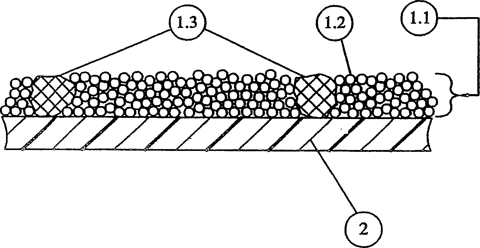
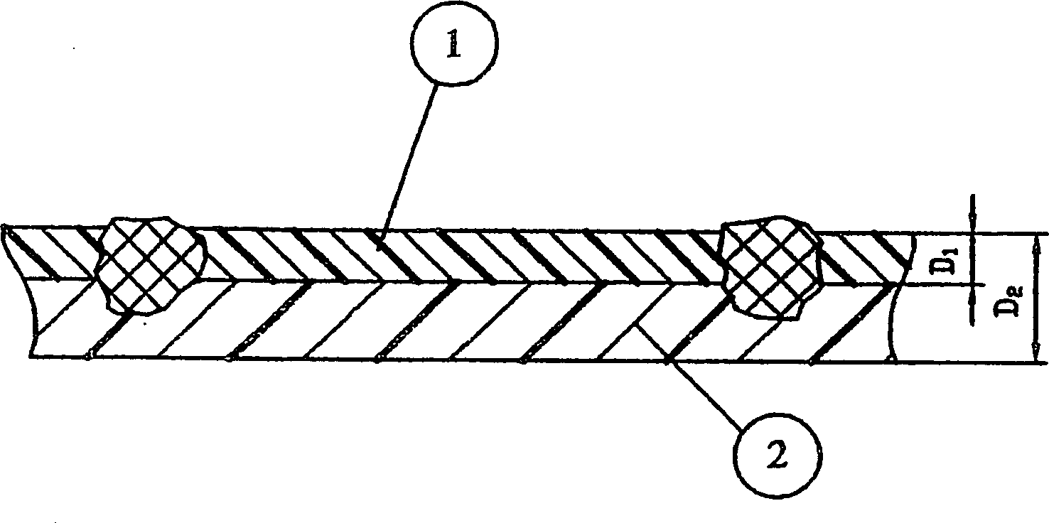
[0022] figure 2 The ground cladding shown in is formed in two layers. This does not preclude an invention in which the upper layer 1 and the lower layer 2 are connected to a base layer arranged below, and the base layer itself can also be made of a polymer or natural material.

[0023] In order to produce this floor covering, it is first envisaged that in the first step, a lower layer made of conductive material is formed. To this end, a rubber mixture composed of the following ingredients is put into a mixer and mixed evenly:

[0024] Butadiene-styrene (SBR) rubber

Glue

High styrene resin (65% styrene

Unit)

Carbon black N770

Chalk

Plasticizer

Zinc oxide

Stearic acid

Paraffin

Anti-aging agent

2-mercaptobenzothiazole

Dibenzothiazole disulfide

Sulfur

11.8%

5.6%

61.5%

14.9%

3.35%

0.7%

0.35%

0.35%

0.2%

0.2%

0.2%

0.85%

100%

[0025] Each of the above data refer...


PUM


Abstract

The invention relates to a floor covering consisting of at least two interconnected layers, comprising an electrically conductive rubber lower layer (2) that is arranged below a light-coloured upper rubber layer (1). The upper layer (1) is perforated in partial sections that are distributed in a pattern over its surface with electrically conductive rubber being embedded in said sections. The upper layer (1) is created by pouring (1.1) first light-coloured particles (1.2), consisting of an electrically insulating rubber onto the lower layer and embedding second particles (1.3) therein, the latter consisting of electrically conductive rubber that is at least pre-vulcanised. The second particles (1.3) have a diameter D, which is determined by screen analysis and is at least equal to the thickness D1 of the upper layer and for practical purposes no greater than the sum of the thickness of the upper and lower layer D2. The first (1.2) and the second particles (1.3) are compressed together and with the lower layer (2) in a pore-free manner and are bonded by vulcanisation. At least one of the second particles (1.3) is present in a surface area unit of 31.7 cm2 of the floor covering, with the proviso that the surface area of the second particles (1.3) constitutes a maximum 50 % of the entire surface area of the floor covering.

Description

Technical field [0001] The present invention relates to a floor covering comprising at least two interconnected layers, including a lower layer made of conductive rubber arranged under a light-colored upper layer made of rubber, wherein the upper layer is in a patterned Part of the area where the form is distributed on the surface is perforated / perforated, and at the same time it is formed by conductive rubber at the perforation. The invention also relates to a method for producing the ground covering. Background technique [0002] Such a floor covering is known from EP 0105074 B1. This floor covering consists of two layers of rubber with contrasting colors arranged on top of each other, wherein the lower layer is conductive and the upper layer is non-conductive. The coating is made in such a way that the material of the upper layer is pre-hardened by early vulcanization before extrusion, and the surface area is removed, and then it is laminated on a soft, unvulcanized rubber On ...

Claims


Application Information

Patent Timeline
04 Oct 2006
Publication
CN1277981C
IPC
D06N7/00; B29D31/00; B32B7/02; E04F15/10; E04F15/18; B29C43/30; B29D99/00; B32B25/00; D06N1/00; H05F3/02
CPC
B29C43/30; E04F2290/048; Y10T428/24694; Y10T428/24372; H05F3/025; B29L2031/7322; Y10T428/24405; Y10T428/24413
Inventors
G·格拉布; K·黑克尔