Fuel battery

A fuel cell and fuel gas technology, applied in the direction of fuel cells, fuel cell additives, fuel cell grouping, etc., can solve problems such as complex sealing structures, achieve uniform flow rates, improve power generation performance, and improve power collection efficiency.

Inactive Publication Date: 2006-11-01
HONDA MOTOR CO LTD
View PDF2 Cites 0 Cited by
  • Summary
  • Abstract
  • Description
  • Claims
  • Application Information

AI Technical Summary

Problems solved by technology

Therefore, these sealing structures are very complex

Method used


Image

  • Fuel battery
  • Fuel battery
  • Fuel battery

Examples


Embodiment Construction

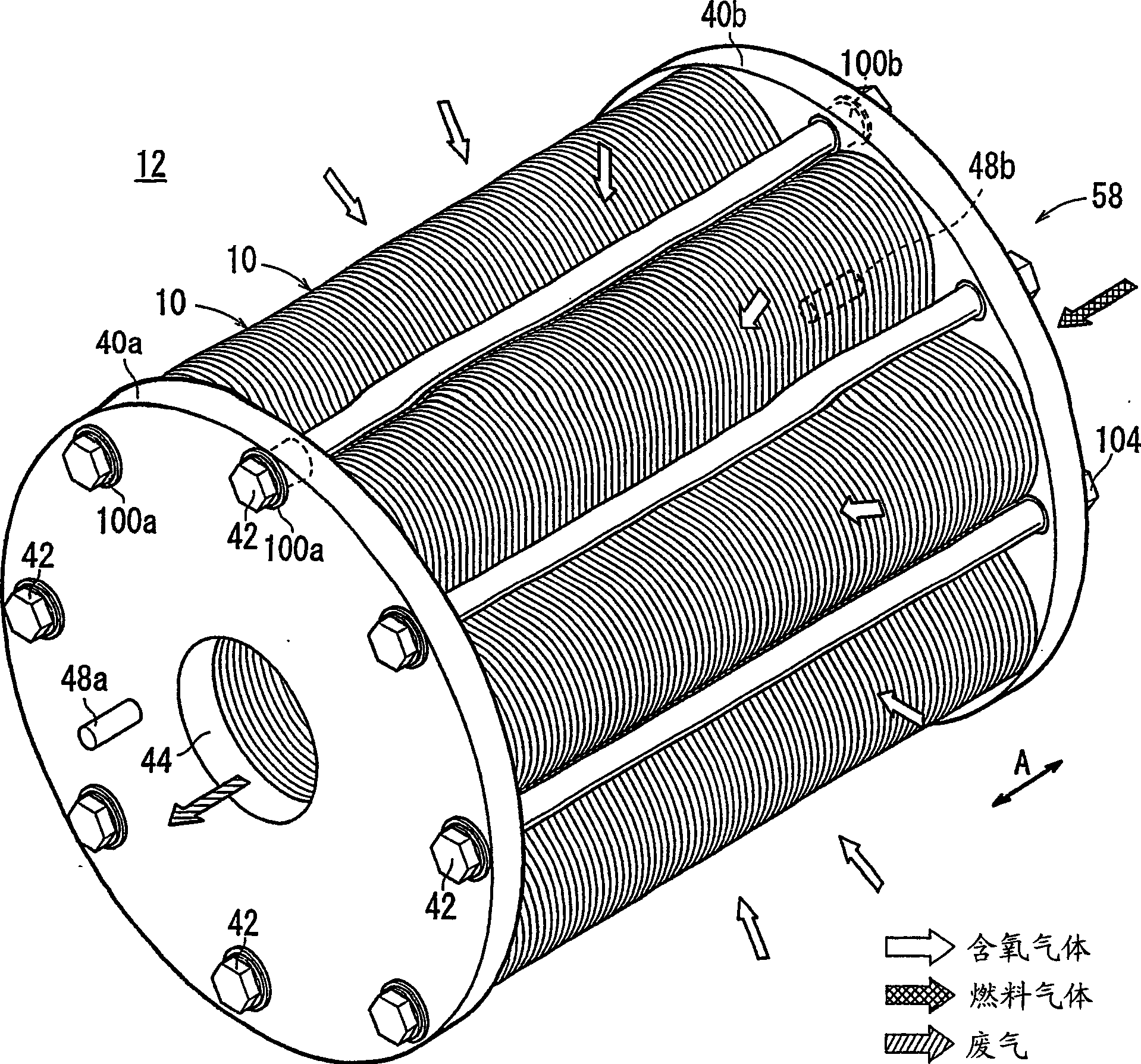
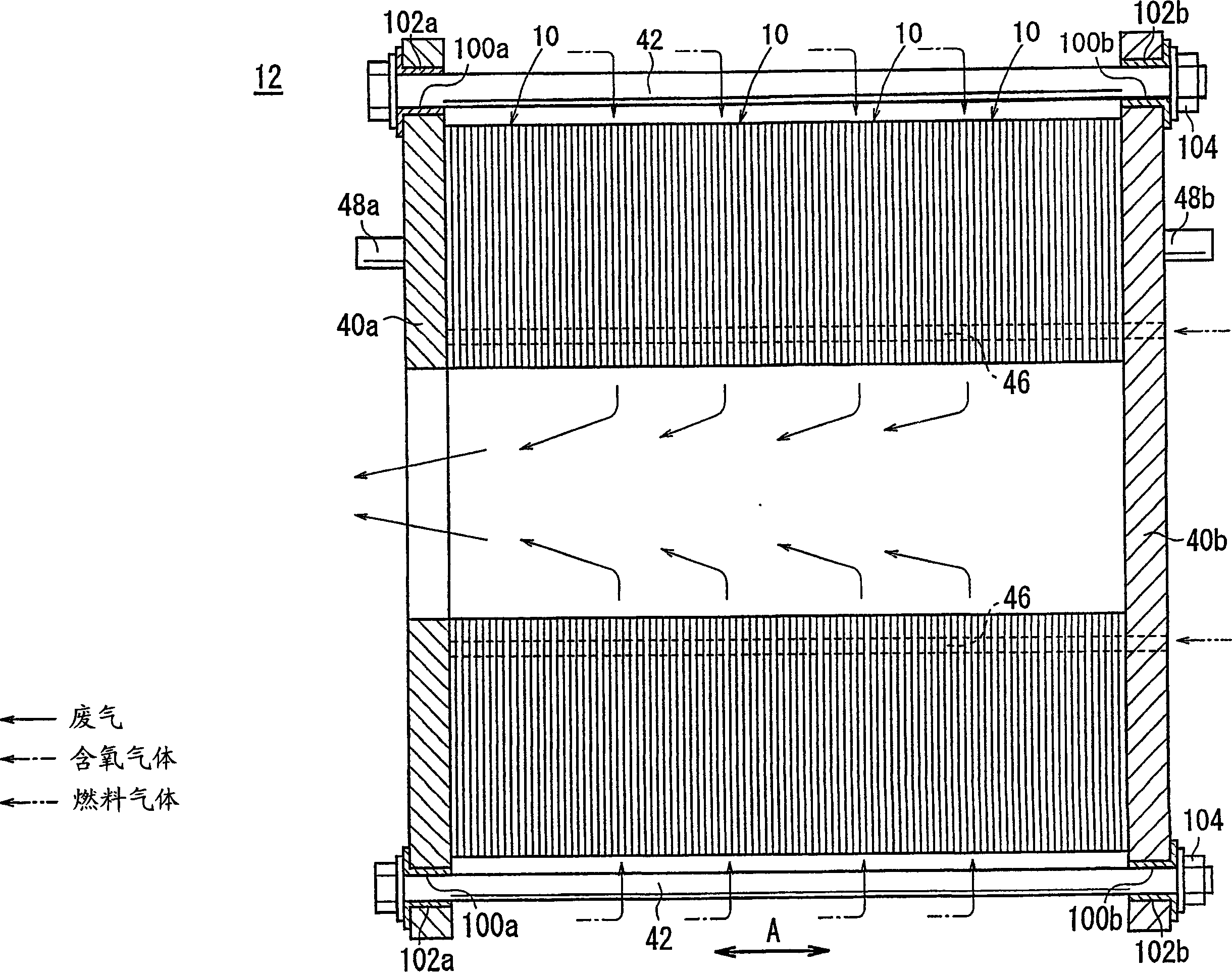
[0042] figure 1 is a perspective view schematically showing a fuel cell stack 12 formed by stacking a plurality of fuel cells 10 according to an embodiment of the present invention, and figure 2 A cross-sectional view of a part of the fuel cell stack 12 is shown.

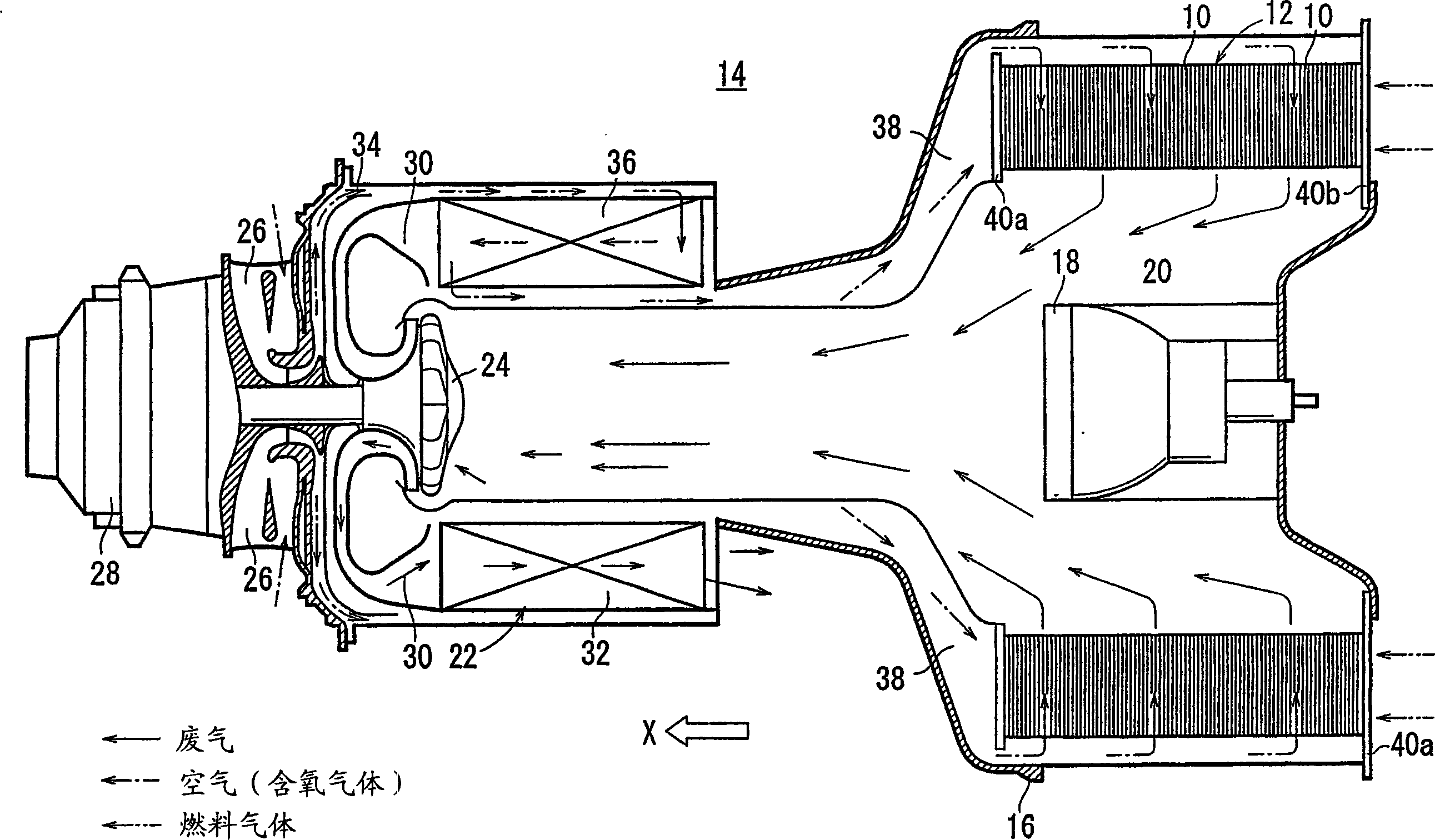
[0043] Fuel cell 10 is a solid oxide fuel cell (SOFC) for stationary and mobile equipment. For example, this fuel cell 10 is mounted on a motor vehicle. exist image 3 In the example of embodiment shown in , the fuel cell stack 12 is used in a gas turbine 14 . exist image 3 , the shape of the fuel cell stack 12 is the same as figure 1 and 2 The ones in are different, but the structure is basically the same.

[0044] The fuel cell stack 12 is disposed within a casing 16 of a gas turbine 14 . The burner 18 is provided at the center of the fuel cell stack 12 . The fuel cell stack 12 discharges the mixed gas of the fuel gas and the oxygen-containing gas after reaction into the chamber 20 toward the burner 1...


PUM


Abstract

A fuel cell (10) includes a pair of separators (58) and a plurality of electrolyte electrode assemblies (56) between the separators (58). Each of the separators (58) includes a pair of plates (60, 62) which are stacked together. A fuel gas channel (67) for supplying a fuel gas to anodes (54) of the electrolyte electrode assemblies (56), an oxygen-containing gas channel (82) for supplying an oxygen-containing gas to cathodes (52) of the electrolyte electrode assemblies (56) are formed between the plates (60, 62). The plates (60, 62) have oxygen-containing gas inlets (77) and fuel gas inlets (88) for supplying the oxygen-containing gas and the fuel gas to central regions of the electrolyte electrode assemblies (56).

Description

technical field [0001] The present invention relates to a fuel cell having a disc-shaped electrolyte electrode assembly interposed between disc-shaped separators. Each electrolyte electrode assembly includes an anode and a cathode and a dielectric between the anode and cathode. Background technique [0002] Typically, solid oxide fuel cells (SOFCs) employ ionically conductive solid oxide electrolytes, such as stabilized zirconia. The electrolyte is interposed between the anode and the cathode to form an electrolyte electrode assembly. The electrolyte electrode assembly is interposed between separators (bipolar plates), and the electrolyte electrode assembly and the separator constitute a fuel cell unit for generating electric power. A predetermined number of fuel cells are stacked together to form a fuel cell stack. [0003] In this fuel cell, an oxygen-containing gas or air is supplied to the cathode. Oxygen in the oxygen-containing gas is ionized at the interface betwe...

Claims


Application Information

Patent Timeline
Patent Type & Authority Patents(China)
IPC IPC(8): H01M8/02H01M8/24H01M8/04H01M8/12
CPCH01M8/0206H01M8/0228H01M8/0247H01M8/0258H01M8/04089H01M8/247H01M2008/1293H01M8/2428H01M8/2432Y02E60/50H01M8/2483H01M8/2457H01M8/02H01M8/0271H01M8/243
Inventor 角田正
Owner HONDA MOTOR CO LTD
Why Eureka
Try Eureka