
Rear projection screen

A projection screen and projection technology, applied in the field of transmissive screens, can solve problems such as reducing screen performance characteristics

Inactive Publication Date: 2001-07-25
3M INNOVATIVE PROPERTIES CO
View PDF4 Cites 8 Cited by
  • Summary
  • Abstract
  • Description
  • Claims
  • Application Information

AI Technical Summary

Problems solved by technology

When a typical rear projection screen is modified to support high resolution, the above trade-off tends to degrade the performance characteristics of the screen

Method used


Image

  • Rear projection screen
  • Rear projection screen
  • Rear projection screen

Examples


example 1

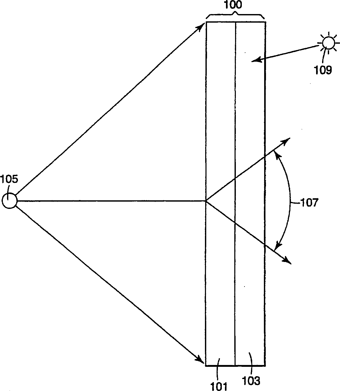
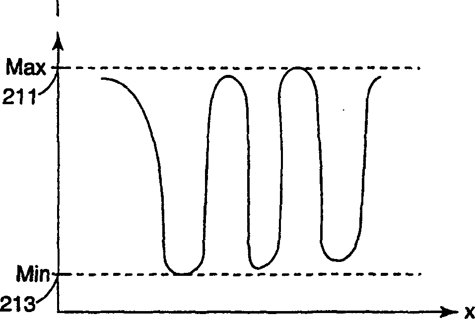
[0077] figure 1 A diffusing element according to the invention and a corresponding increase in modulation depth obtained by combining with a linear polarizer are shown. exist figure 1 In the example of the present invention, the bonding agent is made of 3 kinds of resin components SR9003, SR335 and CN966H90 (Sartomer Company production, Exton, PA) of equal weight plus the photoinitiator (Darocur 4265, Ciba-Geigy Co. .production, Tarrytwon, NY) components. The above resin has a refractive index of about 1.48. Composed of polystyrene and ethylene acrylate copolymers. Particles with a refractive index of 1.54 are dispersed in the resin bond. Particles of the stated type with various refractive indices were produced by Nagase American Corp. (New York, NY). The above mixture was applied to the polycarbonate base to a thickness of approximately 240 μm (9.75 mils). The diffuser element alone has a peak gain of about 0.88, a viewing angle of about 73 degrees and a diffuse reflec...

example 2

[0079] Another embodiment of the invention was made using the mixture described in Example 1. Here, the compound is applied directly to the linear polarizer and cured. The resulting screen assembly has performance comparable to the screen assembly described above, with a similar increase in modulation depth.

example 3

[0081] Eliminate substrates by employing transfer substrates. The transfer substrate was GE8B35 manufactured by General Electric, and included a strong delustering process. A diffuser composition similar to that described in Example 1 was coated on the matte side of a transfer substrate coated with a 2% (IPA) solution of R22764 silicone polyurea fibers (manufactured by 3M Company, St. Paul, MN.). The silicon polyurethane solution has low surface energy and is dried at 70°C before coating the diffuser. After the diffuser was applied to the matte side of the substrate and cured, the assembly was laminated to the linear polarizer and glass support substrate (diffuser side down). The transfer substrate is removed after lamination. After removal of the matte processed transfer substrate, the matte effect remains on the diffuser element. A matte surface means that the specular reflection of the diffusing element is reduced. The overall screen characteristics of the diffuser were...


PUM


Abstract

A rear projection screen assembly is described that includes a diffuser and a polarizer. The diffuser has particles dispersed within a binder. The particles and the binder have different refractive indices and are chosen such that the diffuser spreads light of an initial polarization state a cone of angles while substantially preserving the initial polarization state of the light. The diffuser also substantially depolarizing a portion of the light that is laterally scattered in the diffuser. The polarizer is disposed to receive light transmitted through the diffuser. The polarizer transmits light of the initial polarization state while absorbing a portion of the laterally scattered light that has a different polarization state. The resolution of the overall screen assembly may be made higher while also improving other characteristics of the screen assembly.

Description

field of invention [0001] This invention relates generally to transmissive screens, and more particularly to transmissive screens for rear projection systems. Background technique [0002] Rear projection screens are generally designed to project images projected on the back of the screen into the viewing space. The viewing space of a projection system can be relatively large (eg, a rear projection television) or relatively small (eg, a rear projection data monitor). The performance of a rear projection screen can be described by various characteristics of the screen. Typical screen characteristics used to describe the performance of a screen include gain, viewing angle, resolution, contrast, presence of undesired artifact mottling and speckling, and the like. It is generally desirable for rear projection screens to have high resolution, high contrast and high gain. It is also desirable for the screen to spread light throughout the large viewing space. Unfortunately, as ...

Claims


Application Information

Patent Timeline
Patent Type & Authority Applications(China)
IPC IPC(8): G03B21/60G03B21/62
CPCG03B21/604G03B21/62G03B21/625G02B5/0242G02B5/0278G02B27/28H04N9/3167
Inventor 周鑫鑫P·A·托马斯C·M·布伦那J·C·常R·S·莫什里芙扎德
Owner 3M INNOVATIVE PROPERTIES CO
Learn More