Video imaging device

A technology of imaging equipment and video, applied in TV, image communication, TV system scanning details, etc., can solve problems such as difficult and impossible to adopt design criteria, and achieve the effect of increasing the output voltage level

Inactive Publication Date: 2007-05-02
THOMSON LICENSING SA
View PDF4 Cites 0 Cited by
  • Summary
  • Abstract
  • Description
  • Claims
  • Application Information

AI Technical Summary

Problems solved by technology

However, it is difficult or impossible to apply such design guidelines if the circuit design requires components to operate at the extremes of their usable range

Method used


Image

  • Video imaging device
  • Video imaging device
  • Video imaging device

Examples


Embodiment Construction

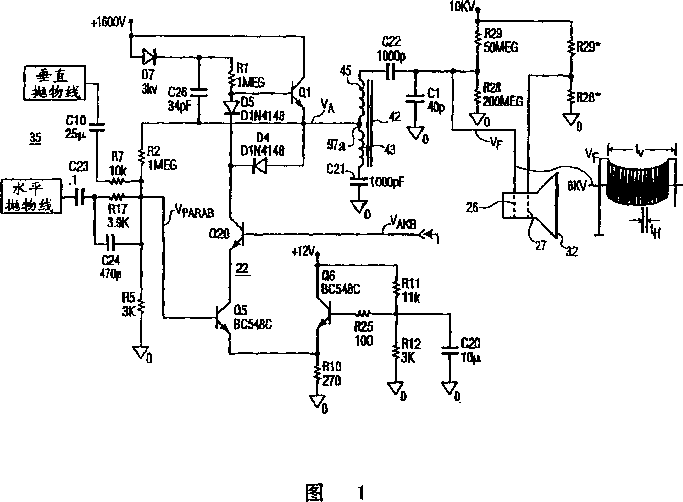
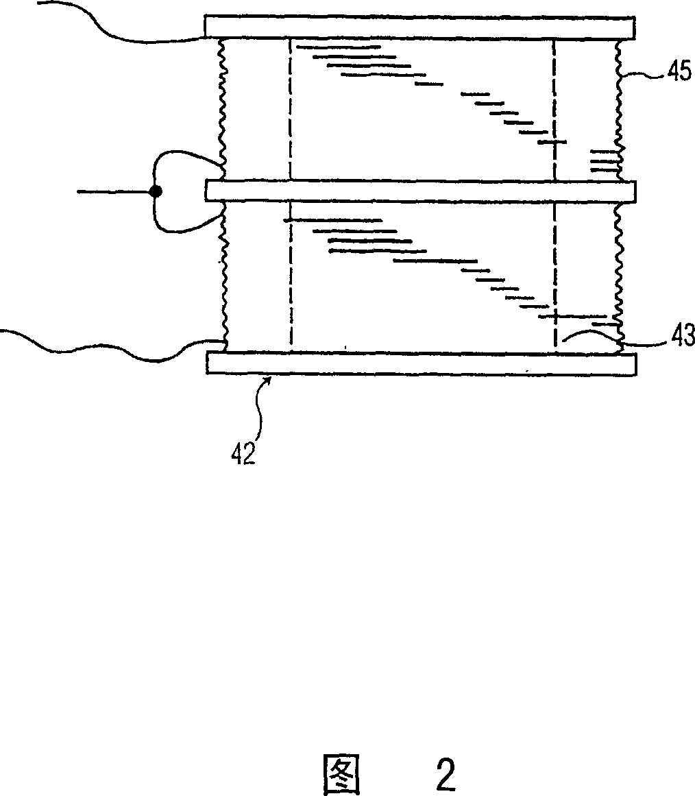
[0021] Figure 1 shows a video imaging device according to an inventive arrangement, wherein a dynamic focus amplifier 22 is adapted to produce a predetermined output amplitude V A The time-varying focus adjustment signal, by using the autotransformer 42, the voltage is boosted to a higher voltage V F . Higher amplitude voltage V F is applied to the dynamic focus electrode 26 of the cathode ray tube 32. High DC voltage V DC is applied to the static focusing electrode 27 at the same time.

[0022] The present invention provides a high voltage dynamic focus signal in a manner that allows the use of amplifier components rated for use at lower voltages, thereby improving device lifetime while controlling cost.

[0023] Focusing electrode 26 is driven with a parabolic voltage at a frequency related to the deflection frequency voltage of electron beam scanning on the screen of CRT 32 . Input parabolic signal V PARAB Produced by source 35 generally shown in FIG. 1, this signal p...


PUM


Abstract

The autotransformer boosts the output of the high voltage amplifier to apply the drive signal to the focus electrodes of the CRT. A parabolic signal at a deflection frequency such as the horizontal scanning frequency is obtained or generated and applied as an input to an amplifier. The output of the amplifier is coupled to the center tap of the autotransformer. One winding is coupled in series to the focusing electrode, and the other winding is AC coupled to ground by a capacitor in parallel with the amplifier output. The voltage transformer boosts the output voltage of the amplifier and reduces the required voltage rating of the transistors in the amplifier.

Description

technical field [0001] The present invention relates to a dynamic focus adjustment circuit for a cathode ray tube, in particular the use of an autotransformer to boost the output voltage of a gated high voltage amplifier. Background technique [0002] In a cathode ray tube used for display or projection, one or more electron guns emit electrons that are electrostatically attracted to the phosphors of the fluorescent screen of the cathode ray tube. When the time-varying magnetic field generated by the deflection yoke scans the electron beam in a raster pattern, the amplitude of the electron beam current is changed, thereby changing the brightness of the phosphor. Electron beams tend to diverge due to electrostatic repulsion. As the electrons in the CRT electron beam move from the cathode to the screen (anode), the focusing device associated with the electron gun causes the divergent electrons in the scanning electron beam to converge again to the focal point. The precise po...

Claims


Application Information

Patent Timeline
IPC IPC(8): H04N3/26G09G1/00
CPCH04N3/26H04N3/16
Inventor R·E·费恩斯勒R·J·格里斯
Owner THOMSON LICENSING SA
Why Eureka
Try Eureka