LED backlight system of packing LED using three primary colors (RGB)
A technology of LED light source and backlight system, applied in the field of backlight system, can solve the problems of uniform white light, inability to obtain, not using light diffuser at the same time, etc.
- Summary
- Abstract
- Description
- Claims
- Application Information
AI Technical Summary
Problems solved by technology
Method used
Image
Examples
Embodiment 1
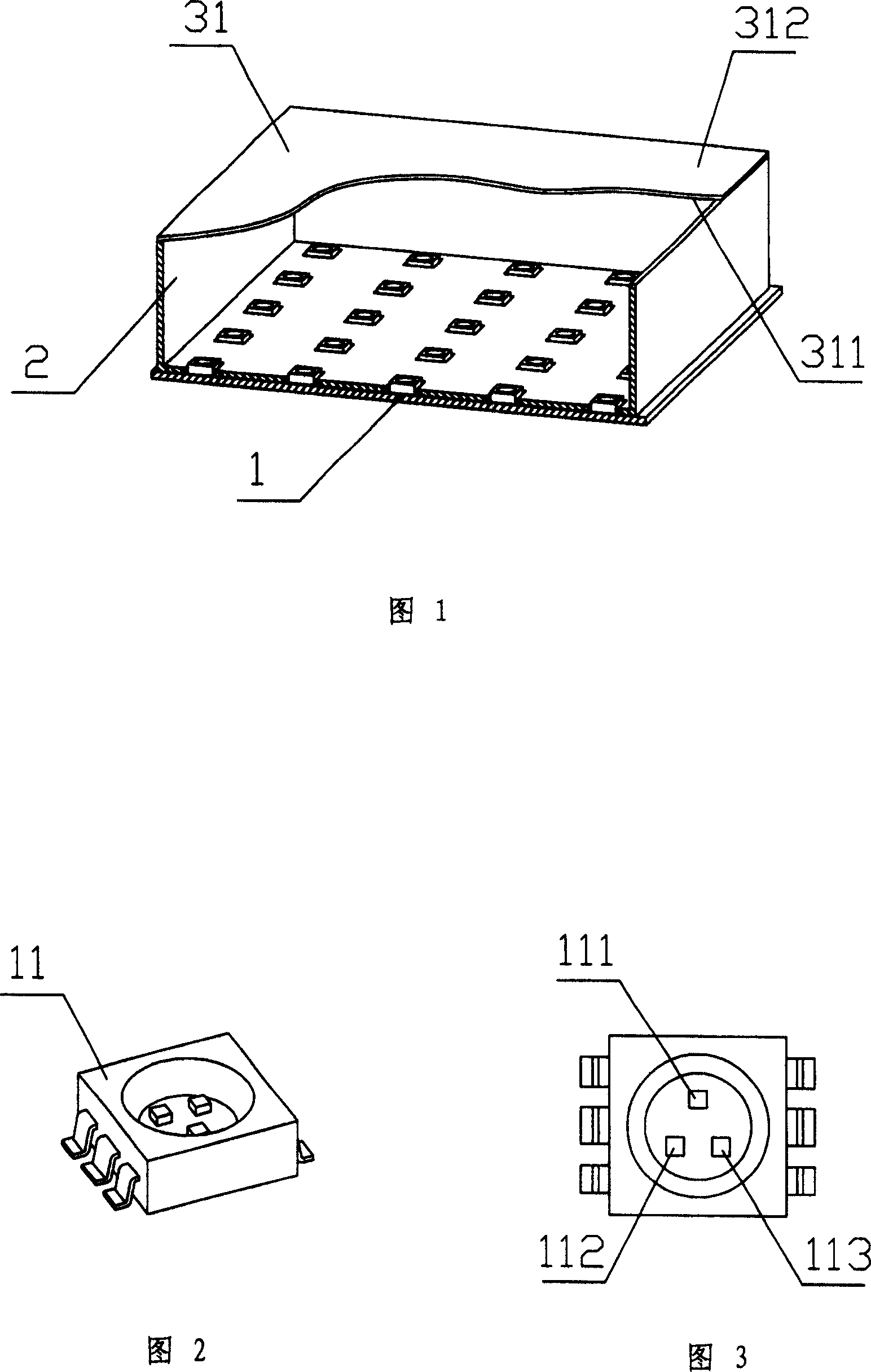
[0034] Please refer to FIG. 1 , the structure of the backlight system from bottom to top is: a light source module 1 , a reflection box 2 and a scattering layer 31 .
[0035] Please refer to Fig. 2 and Fig. 3, the LED light source 11 packaged in three primary color units, the red, green and blue three-color chips 111, 112 and 113 packaged in each LED, when the rated operating current is 20mA, the dominant wavelengths are respectively: 615~ 625nm, 520~535nm, 460~475nm, the light intensity is: 180~450mcd, 450~1120mcd, 71~180mcd respectively; the LED adopts the form of chip mounting (SMT), which is a package structure of 6 leads, and each 2 leads are independent control a chip. The outgoing angle (FWMH) of the light is 120°.
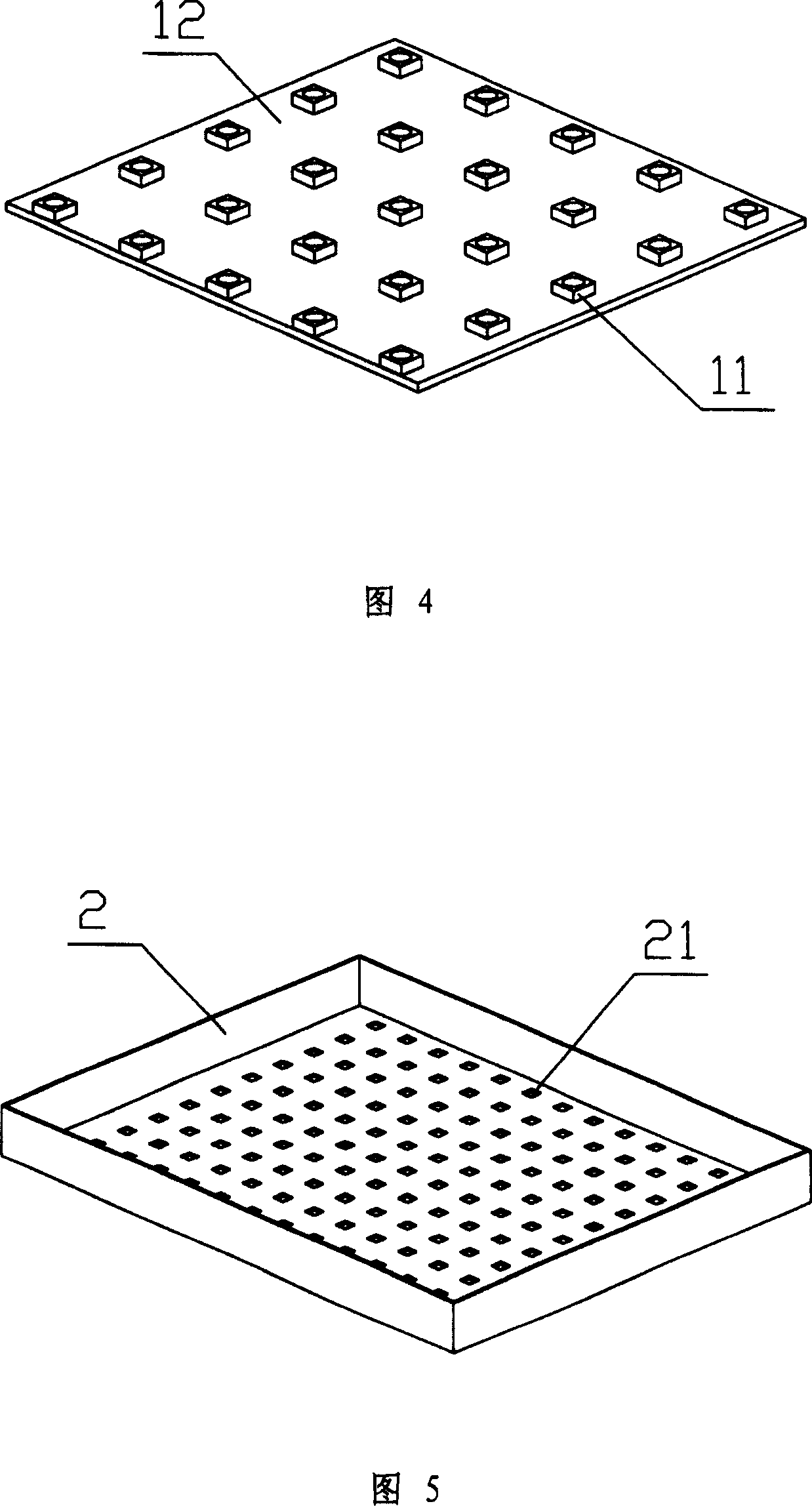
[0036] Please refer to Fig. 4, several LED light sources packaged with the above-mentioned three primary color units are soldered to an aluminum-based PCB 12 by SMT mounting process. The aluminum-based PCB has designed corresponding circuits according to t...
Embodiment 2
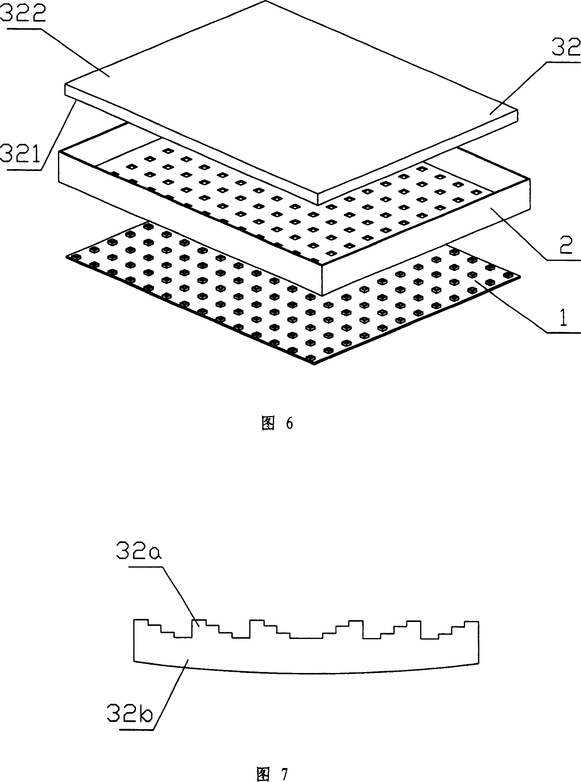
[0046] Please refer to FIG. 6 , the composition structure of the backlight system from bottom to top is: light source module 1 , reflection box 2 and refraction-diffraction mixing light guide plate 32 .
[0047] The light source module of the LCD backlight system is the same as the first embodiment.
[0048] On one side of the opening of the reflection box, a refraction-diffraction mixing light guide plate 32 is installed. The function of the light guide plate is to mix and diffuse the light irradiated on the incident surface 321 , so as to obtain relatively uniform light on the light emitting surface 322 .
[0049] The refraction-diffraction hybrid system is composed of a diffractive optical device and a traditional refractive optical device, that is, the surface of the substrate is made into a diffractive optical device 32a, and the substrate itself is made into a refractive optical element 32b. Specifically, the light guide plate itself is a refractive element, and some mi...
Embodiment 3
[0053] It basically follows the same structure as the second embodiment, except that there are several grooves 3211 on the incident surface 321 of the refraction-diffraction mixing light guide plate 32 , as shown in FIG. 8 . The position and shape of the groove correspond to the position and shape of the LED light source on the aluminum-based PCB in the light source module, and the function is to collect the light emitted by the LED.
[0054] After installation, the LED light source on the light source module is directly embedded in the groove 3211 on the incident surface 321 of the refraction-diffraction mixing light guide plate, the light emitted by the LED directly enters the light guide plate through the groove, is mixed and diffused in the light guide plate, and then flows out The emitting surface 322 can obtain uniform light with a suitable color temperature.
[0055] Since the LED light source is directly embedded in the groove on the incident surface of the light guide...
PUM
| Property | Measurement | Unit |
|---|---|---|
| length | aaaaa | aaaaa |
Abstract
Description
Claims
Application Information
 - R&D
- Intellectual Property
- Life Sciences
- Materials
- Tech Scout
- Unparalleled Data Quality
- Higher Quality Content
- 60% Fewer Hallucinations
Browse by: Latest US Patents, China's latest patents, Technical Efficacy Thesaurus, Application Domain, Technology Topic, Popular Technical Reports.
© 2025 PatSnap. All rights reserved.Legal|Privacy policy|Modern Slavery Act Transparency Statement|Sitemap|About US| Contact US: help@patsnap.com


