Fluidizer of fluidized bed
A fluidized device and fluidized bed technology, applied in the field of fluidized bed fluidized devices, can solve the problems of high energy consumption and large resistance, and achieve the effects of improving desulfurization efficiency, improving load adaptability and saving investment.
- Summary
- Abstract
- Description
- Claims
- Application Information
AI Technical Summary
Problems solved by technology
Method used
Image
Examples
Embodiment 1
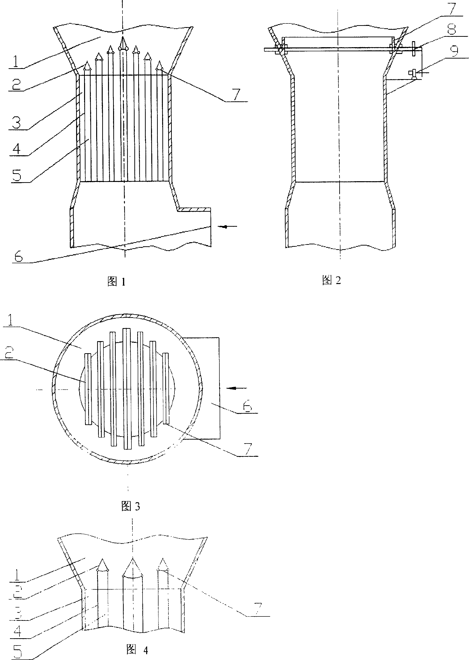
[0018] It is used for flue gas desulfurization of medium-temperature or low-temperature semi-dry circulating fluidized bed spraying lime slurry. The minimum flow rate in venturi pipe throat 3 is 30% of the rated load. And perpendicular to the flue gas inlet 6, the left and right ends are respectively welded to the inner wall of the Venturi tube throat 3 and the Venturi tube expansion section 1. There are seven groups of branch flues 5 that can be closed, and their outlets gradually decrease from the center to the wall. The cross-sectional area of the central branch flue 5 accounts for 15% of the cross-sectional area of the Venturi throat pipe 3, and the cross-sectional areas of the other symmetrical flues are equal, and the cross-sectional areas of the closed flue account for 9%, 7%, and 6.5% respectively . The adjustment baffle 2 is in contact with the deflector 4, its rotation can be manually adjusted, and the shape of the sealing baffle 7 can be controlled by the servo ...
Embodiment 2
[0021] The difference between this embodiment and Embodiment 1 is that there are three groups of branch flues 5 that can be closed, and their outlet heights are equal to 15% of the total area of the horizontal cross-sectional area of the central flue, and the other two groups are 10% of the load at 73 When changing between %~85%, only the central branch flue 5 is closed; when between 55%~73% of the rated load, close the three branch flues 5 and the structure size of the other is the same as that of embodiment 1
Embodiment 3
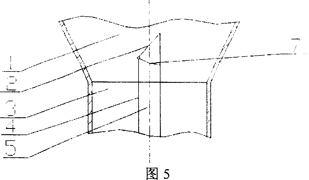
[0023] The difference between this embodiment and Embodiment 1 is that there is only one closable branch flue 5, which accounts for 20% of the total cross-sectional area; 5 The deflector 4 on the other side is extended so that it can contact the closed adjustment baffle 2 and the sealing baffle 7 is welded to the inner wall of the deflector 4 and the Venturi tube diverging section 1. When the adjustment baffle 2 is closed, they Together, only the triangular prisms with lower openings close the flue at 85% of the rated load, so the adjustment range of the load is 68% to 85% of the rated value, and the rest of the structural dimensions are the same as in Embodiment 1.
PUM
 Abstract
Description
Claims
Application Information
 - R&D
- Intellectual Property
- Life Sciences
- Materials
- Tech Scout
- Unparalleled Data Quality
- Higher Quality Content
- 60% Fewer Hallucinations
Browse by: Latest US Patents, China's latest patents, Technical Efficacy Thesaurus, Application Domain, Technology Topic, Popular Technical Reports.
© 2025 PatSnap. All rights reserved.Legal|Privacy policy|Modern Slavery Act Transparency Statement|Sitemap|About US| Contact US: help@patsnap.com


