
Cross-coupling connector of multi-wavelength encoded optical switch and interval ring optical fibre

An annular gap and cross-coupling technology, applied in the coupling of optical waveguides, etc., can solve the problems of slow transmission speed, complex equipment, large loss, etc., and achieve the effects of low cost, reduced system cost, and long working life.

Inactive Publication Date: 2002-01-09
王又良 +2
View PDF0 Cites 5 Cited by
  • Summary
  • Abstract
  • Description
  • Claims
  • Application Information

AI Technical Summary

Problems solved by technology

[0003] In terms of information technology, more and more information shows that after the Internet, one of the largest industries in information is photonics, which uses optical methods to carry out the Internet, with fast speed and large capacity, and replaces routers in the switching network with optical fiber devices. It can realize all-optical network interconnection, but at present, the replacement of routers in the switching network with optical devices still has the disadvantage of the so-called "electronic bottleneck", that is, the cross-connector of the digital synchronous switch needs to demodulate the electrical signal from the optical carrier, and then After the electronic cross-connection, re-realize the optical / electrical conversion and enter the optical transmission network, not only the equipment is complex, the transmission speed is slow, and the loss is large

Method used


Image

  • Cross-coupling connector of multi-wavelength encoded optical switch and interval ring optical fibre
  • Cross-coupling connector of multi-wavelength encoded optical switch and interval ring optical fibre
  • Cross-coupling connector of multi-wavelength encoded optical switch and interval ring optical fibre

Examples


Embodiment Construction

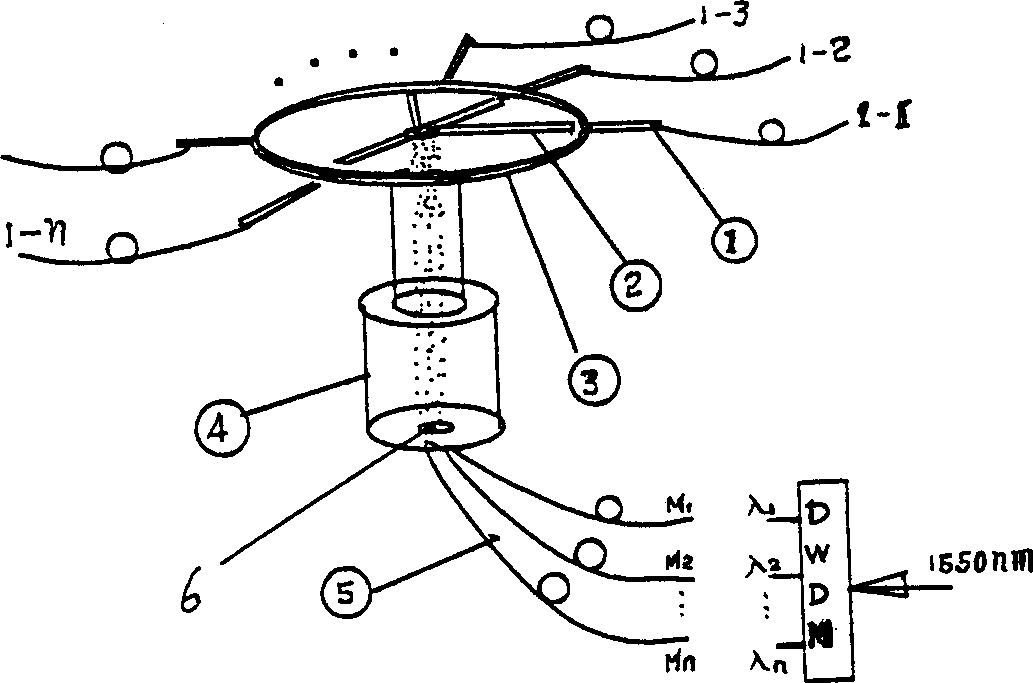
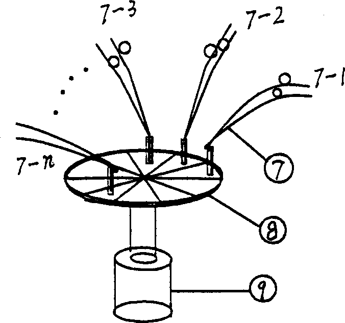
[0019] Please refer to the attached figure 1 As shown, the m optical channels are divided into λ 1 , lambda 2 , lambda 3 ...λ n m×n independent optical channels, these m×n independent optical channels are made into a ring-shaped coaxial optical cross splitter after being passed through the collimator 2, and the optical cross splitter surrounds a rotating shaft 4, in the order of the channels, will lambda 1 , lambda 2 , lambda 3 ...λ n A collimator is horizontally arranged on the outer side of the disk 3 on the electromagnetic rotating shaft, and in the groove on the disk 3, a single-mode optical fiber is arranged, and the end face of the single-mode optical fiber has a very small gap with the end face of the collimator arranged on the outer side of the disk 3. The other end of the single-mode optical fiber passes through the inner hole 6 in the center of the electromagnetic shaft 4, and is respectively connected to the external wavelength division multiplexer, M1, M2, M...


PUM


Abstract

Multiple optical fibres are divided into n individual optical channels. After passing through collimator, an optical cross distributor with ring shape is formed. Said n individual optical channels are sequentially arranged at external side of disk on rotary axle. The single-mode optical fibres are arranged on said disk and addressed by high-speed deflection driven by coaxial small-inertia deflecting axle. After it is aligned with collimator, a space-division cross connector is formed. Said optical coupling switch is formed by the small gaps between coaxial rings. Said encode switch is a partition encoded full-reflection medium membrane driven by a coaxial rotor of optical scanner.

Description

technical field [0001] A multi-wavelength coded optical switch and an annular gap optical fiber cross-coupling connector, belonging to optical fiber communication [0002] technology field. Background technique [0003] In terms of information technology, more and more information shows that after the Internet, one of the largest industries in information is photonics, which uses optical methods to carry out the Internet, with fast speed and large capacity, and replaces routers in the switching network with optical fiber devices. It can realize all-optical network interconnection, but at present, the replacement of routers in the switching network with optical devices still has the disadvantage of the so-called "electronic bottleneck", that is, the cross-connector of the digital synchronous switch needs to demodulate the electrical signal from the optical carrier, and then After the electronic cross-connection, re-realize the optical / electrical conversio...

Claims


Application Information

Patent Timeline
Patent Type & Authority Applications(China)
IPC IPC(8): G02B6/26G02B6/35
Inventor 王又良王海彪曲世浦
Owner 王又良
Learn More