Pulse type counting method

A pulse counting and counter technology, applied in the fields of pulse counting and digital information processing, can solve the problems of complex circuit structure, insufficient stability, and difficult to popularize, and achieve the effect of no logic errors, simple structure, and getting rid of software instability.

Inactive Publication Date: 2002-02-20
SHANGHAI INST OF MICROSYSTEM & INFORMATION TECH CHINESE ACAD OF SCI
View PDF0 Cites 12 Cited by
  • Summary
  • Abstract
  • Description
  • Claims
  • Application Information

AI Technical Summary

Problems solved by technology

Due to the complexity of DSP itself, it will inevitably cause a series of problems such as high cost, comp...

Method used


Image

  • Pulse type counting method
  • Pulse type counting method
  • Pulse type counting method

Examples


Embodiment 1

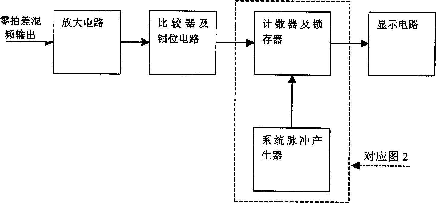
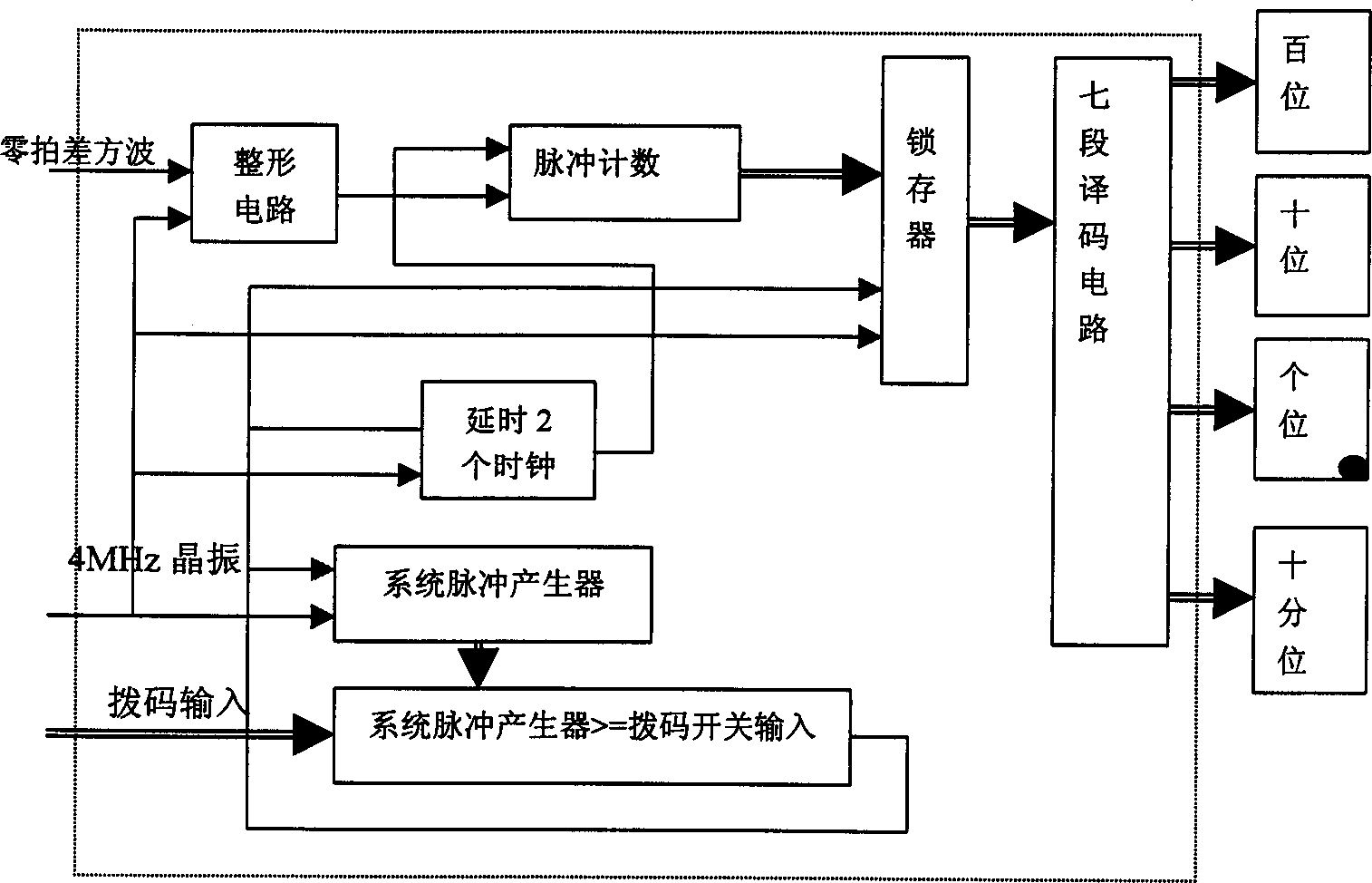
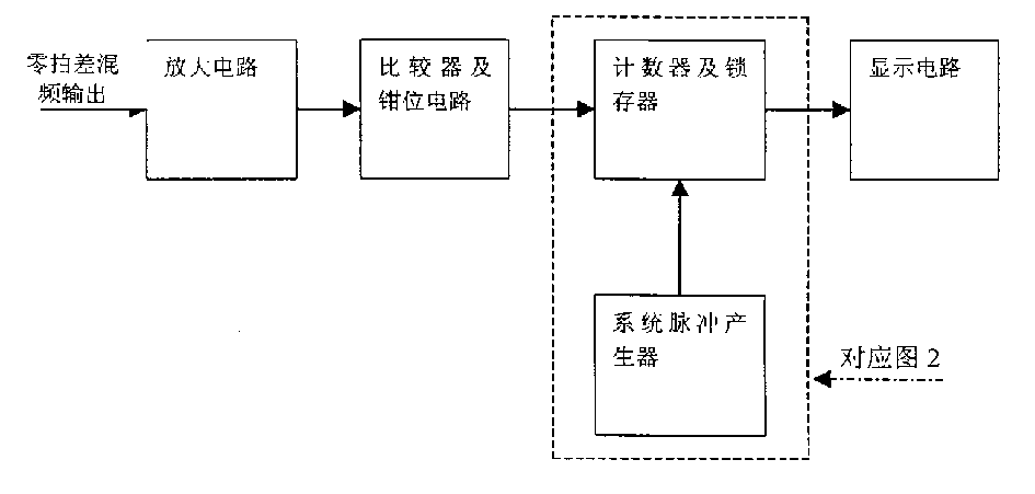
[0036] Assuming that the corresponding frequency at one meter of a radar is 5KHz, first find its reciprocal T=0.0002, and then multiply it by 100 to get T 100=0.02 seconds, that is, 20 milliseconds, the corresponding BCD code is 0010 0000.0000 0000 (accurate to 0.01 milliseconds). Input this value through the dial switch as the counting time threshold, and the count value of the system pulse generator is the same as the input dial switch value Comparison, when the counter value is greater than the input value of the dial code, the comparator outputs a high level, which is used as the synchronous clear signal of the system pulse generator and the latch enable signal of the latch, and after two system clocks After a delay, it acts as an asynchronous clear signal for the pulse counter. The pulse counter uses the zero beat square wave signal as input, records the number of the square wave, and when the latch receives the latch enable signal, the count value of the pulse counter is...

Embodiment 2

[0038] If the frequency corresponding to one meter of radar is 7.2KHz, then T 100 = 13.89 milliseconds, the corresponding BCD code is 0001 0011.1000 1001, you only need to manually set the value of the DIP switch to this value. It is simple and convenient to realize. All the other are with embodiment 1.


PUM


Abstract

The method can be used as a substitute for prior art digital information processing method of radar system. The beat frequency signal from fore-end mixer is transferred to amplifying section of IF circuit, after being amplified, it is transfered into comparer. The positve and negative pulse signal from the mixer is clamped in 0-5V (square wave signal) by clamping circuit, after being synchronized, the pulse signal is transfered into counter which is controlled by system pulse generator to do zero clearing at fixed time, to output count value into latch to be drived by driving circuit to display on display circuit. The key of this invention is the realization of comparer, counter, latch and system pulse generator. Said invention overcomes instability of software and complexity of algorithm since that pure hardware design enhances the speed of system responding. It has simple structure, high stability and easy to integrated radar system.

Description

technical field [0001] The invention provides a pulse counting method, more precisely relates to a digital information processing method that can replace the existing radar system. It belongs to the technical field of frequency modulation continuous wave radar. Background technique [0002] The signal processing part of the existing radar system is mostly implemented by a digital signal processor (DSP). Use DSP for software programming, use some complex algorithms, and get the required results according to the radar echo information. In the existing anti-collision radar system, DSP is used to obtain the distance of the measured target. Due to the complexity of DSP itself, it will inevitably cause a series of problems such as high cost, complex circuit structure, and insufficient stability. It is difficult to promote in practical application and production. Contents of the invention [0003] The purpose of the present invention is to provide a kind of pulse counting met...

Claims


Application Information

Patent Timeline
IPC IPC(8): H03K21/02H03K21/16
Inventor 李玉芳孙晓玮夏冠群
Owner SHANGHAI INST OF MICROSYSTEM & INFORMATION TECH CHINESE ACAD OF SCI
Why Eureka
Try Eureka