Device for obtaining slag flow-out signal in casting steel with ladle

A technology of pouring steel and molten slag, which is applied in the field of non-electricity detection, can solve the problems of slow temperature change speed and outflow speed, which affects the detection effect of the device, and only occurs at the end of steel pouring, so as to achieve high accuracy and increase anti-interference performance , good reliability

Inactive Publication Date: 2002-07-24
ZHEJIANG UNIV
View PDF0 Cites 9 Cited by
  • Summary
  • Abstract
  • Description
  • Claims
  • Application Information

AI Technical Summary

Problems solved by technology

The device based on the above structure has the following disadvantages: 1. The simple excitation source has no automatic adjustment function, which cannot adapt to the fact that the replacement sensor has manufacturing errors and the diameter of the ladle expands after multiple pouring operations; 2. Due to the fact that the ladle With a large heat capacity, the temperature change speed of the sensor part is much slower than the slag outflow speed, and the slag outflow only occurs at the end of pouring steel. In fact, t

Method used


Image

  • Device for obtaining slag flow-out signal in casting steel with ladle
  • Device for obtaining slag flow-out signal in casting steel with ladle
  • Device for obtaining slag flow-out signal in casting steel with ladle

Examples


Embodiment Construction

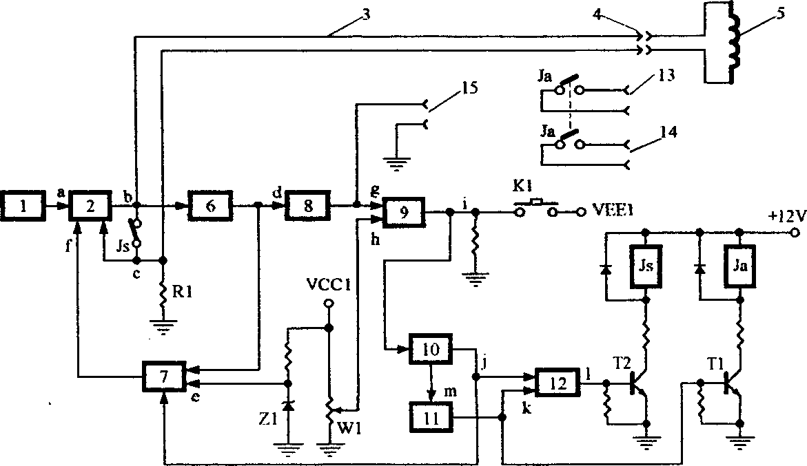
[0018] Structural block diagram of the present invention is as figure 1 As shown, it includes a sine wave oscillator 1, a transconductance amplifier circuit 2, a peak detector circuit 6, a numerically controlled resistor network voltage divider 7, a filter amplifier circuit 8, a voltage comparator 9, a bistable trigger 10, a monostable Trigger 11, RS trigger 12, relay; the output of sine wave oscillator 1 is connected to sensor 5 through transconductance amplifier 2, twin-core cable 3, high temperature connector 4, and the output of transconductance amplifier 2 is through peak detection circuit 6, The filter amplifier circuit 8 is connected to the voltage comparator 9, the other input terminal of the voltage comparator 9 is connected to the adjustable positive potential, the output terminal is connected to the negative potential and the bistable trigger 10 through the button, and the input of the digitally controlled resistor network voltage divider 7 Connect the output termin...


PUM


Abstract

A device for obtaining the slag flow-out signal in casting steel with ladle is composed of sine wave oscillator, transconductance amplifier, peak detector, numerally controlled resistance network as voltage divider, filter amplifier, voltage comparator, bi-stable trigger, mono-stable trigger, Rs trigger and relay. Its advantages are high reliability and correctness, maximal steel output and minimal slag flowing in ladle.

Description

technical field [0001] The invention relates to a non-electricity detection technology, in particular to a device for acquiring molten slag outflow signals during ladle pouring. Background technique [0002] The present invention applies the non-electrical measurement technology to establish an automatic detection device for the non-oxidation continuous casting production line. When the pouring of the ladle is nearing the end, once the slag flows out, the sensor installed at the tap hole of the device will feel the transformation of the steel slag. And convert this conversion into electric signal, after circuit processing and amplification, it becomes the driving signal for slag lowering alarm and closing ladle sliding nozzle, so as to realize automatic ladle closing with maximum steel output and minimum slag outflow effect. [0003] In the prior art field, the published application date is February 22, 1986, and the application number is the "slag de...

Claims


Application Information

Patent Timeline
IPC IPC(8): B22D11/18
Inventor 邱东明
Owner ZHEJIANG UNIV
Why Eureka
Try Eureka