
Motor control device

A control device and motor technology, applied in AC motor control, electronic commutation motor control, single motor speed/torque control, etc., can solve the complex calculation of reactive power command value, easy stop of motor rotation, unstable action, etc. problem, to achieve the effect of short feedback control cycle, large operating range and simple debugging

Inactive Publication Date: 2002-10-16
PANASONIC CORP
View PDF2 Cites 13 Cited by
  • Summary
  • Abstract
  • Description
  • Claims
  • Application Information

AI Technical Summary

Problems solved by technology

However, in the feedback control that detects the zero-cross point every 60 degrees electrical angle, there is a large detection hysteresis due to sample-and-hold
The problem with this detection hysteresis is that, especially in the frequency range where the motor speed is low, the operation will be unstable, resulting in a step-out phenomenon, and the motor will easily stop rotating.
However, since the voltage applied to the motor is approximately proportional to the rotation speed, the reactive power command value must be changed according to the change in the rotation speed, and since the motor parameters are used to generate the command value, it is the same as the second conventional technology. , must be corrected according to changes in parameters, so the calculation of the reactive power command value is complicated, and as a result, the entire calculation amount increases, and a high-priced microcomputer or DSP must be used
In addition, similar to the second conventional technology, in order to control motors with different parameters, each parameter must be adjusted, and it is difficult to directly apply to motors with different parameters.
Another problem is that this conventional technology is a control method in which the output torque is always at the maximum, and because the field-weakening control used when the voltage is insufficient cannot be performed, the speed range is limited.

Method used


Image

  • Motor control device
  • Motor control device
  • Motor control device

Examples


no. 1 Embodiment

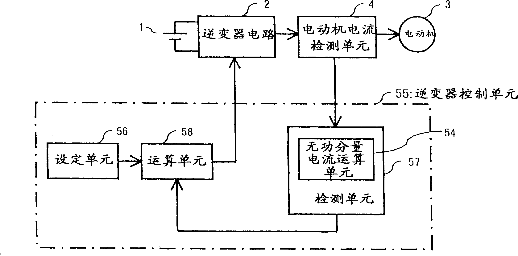
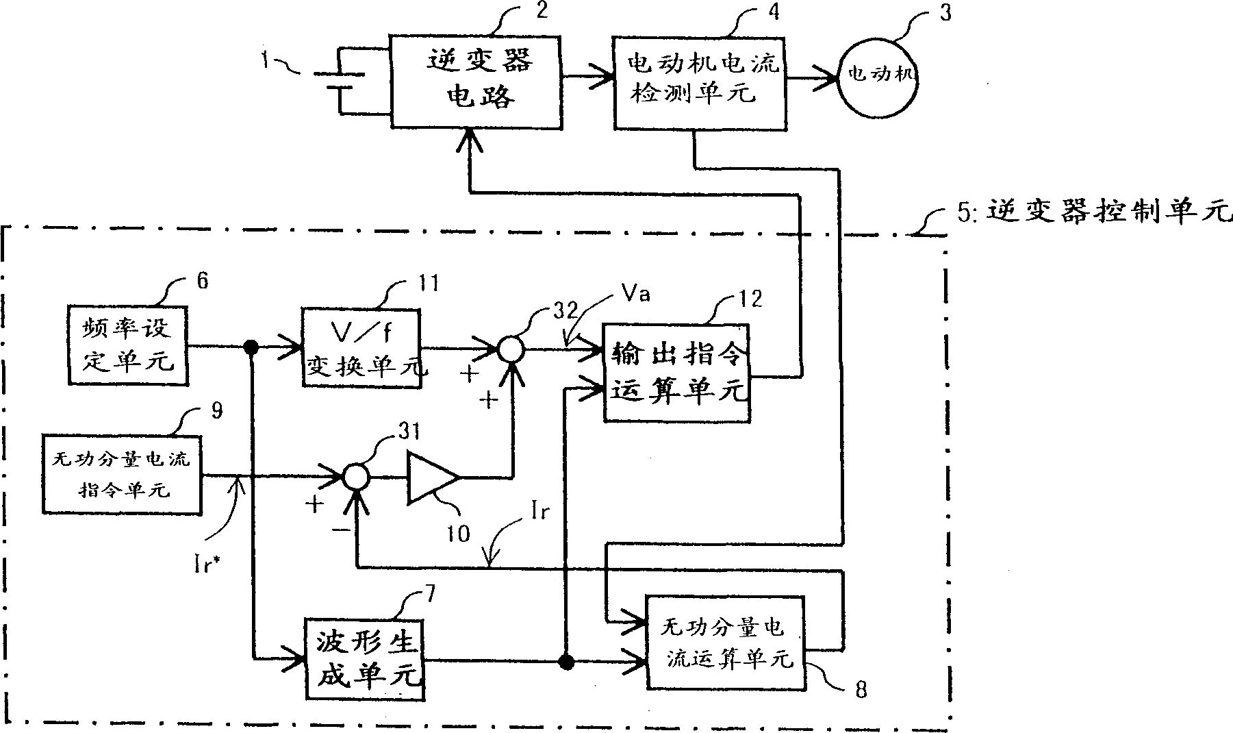
[0058] figure 1 Shown is a block diagram showing the basic configuration of the motor control device according to the first embodiment of the present invention. exist figure 1 Among them, the DC of the DC power supply 1 is added to the inverter circuit 2, converted into AC, and supplied to the motor 3 through the motor current detection unit 4. The motor 3 is, for example, a synchronous brushless motor and does not have a position sensor for detecting the rotor position. The output of the motor current detection unit 4 is used as the input of the detection unit 57 having the reactive component current calculation unit 54 of the inverter control unit 55 . In the detection unit 57, the reactive component current is calculated, and the detection value is output according to the value, and added to the calculation unit 58, and the setting unit 56 is used to set various settings for controlling the inverter circuit 2, which will be described in detail later. A fixed value, which...

no. 2 Embodiment

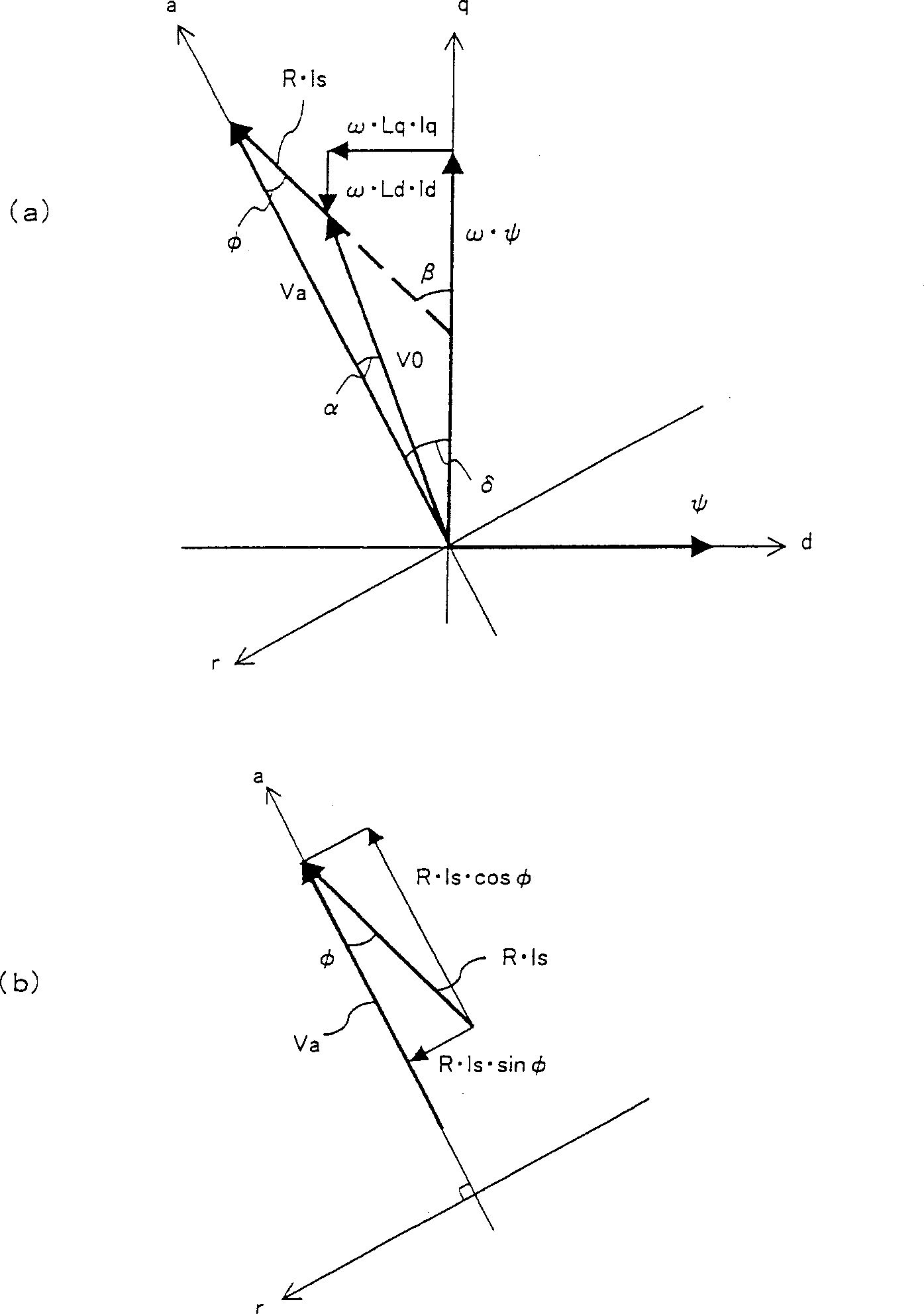
[0071] Figure 4 It is a block diagram of a motor control device according to a second embodiment of the present invention. In the figure, the inverter control unit 5A is the figure 2 In the inverter control unit 5, an active component current calculation unit 13 and a phase difference Φ calculation unit 14 are added, and the reactive component current command unit 9 is changed into a phase difference Φ command unit 15. Other configurations are the same as those of the aforementioned first embodiment. The phase difference Φ is the phase difference between the applied voltage command value Va and the motor current Is. The active component current calculation unit 13 obtains the active component current Ia by the calculation of the formula (4). Ia = 2 3 × [ Iu × sin θ + Iv × sin ( ...

no. 3 Embodiment

[0080] Figure 5 It is a block diagram of a motor control device according to a third embodiment of the present invention. In the figure, the inverter control unit 5B is the second embodiment Figure 4 The phase difference Φ calculation unit 14 in the inverter control unit 5A is replaced with a phase difference d calculation unit 16 , and the phase difference Φ command unit 15 is replaced with a phase difference d command unit 17 . The phase difference α computing unit 16 calculates the phase difference α from the output of the reactive component current computing unit 8, the output of the active component current computing unit 13, and the output of the adding unit 32, namely the voltage command value added by the motor, according to formula (7). α = Tan - 1 ( R × Ir Va ...


PUM


Abstract

The present invention provides a motor control device capable of stably and efficiently driving a synchronous motor without a position sensor with simple control. Command value, obtain the error voltage, and compensate the V / f characteristic of the motor.

Description

technical field [0001] The present invention relates to a motor control device for controlling a synchronous motor without a position sensor Background technique [0002] A representative synchronous motor without a position sensor is a brushless motor. There has been known a method of driving a brushless motor in which an induced voltage is detected in order to detect a rotor position of the brushless motor, and the brushless motor is driven based on it. As a driving method of the brushless motor, there are rectangular wave drive in which the brushless motor is driven with a rectangular wave current, and sinusoidal wave drive in which the brushless motor is driven with a sinusoidal current. In rectangular wave drive, since the current waveform is a rectangular wave, the efficiency, vibration and noise of the motor are worse than those in sine wave drive. In sine wave drive, the zero crossing point of the motor current will be detected. Feedback control is performed on the...

Claims


Application Information

Patent Timeline
Patent Type & Authority Applications(China)
IPC IPC(8): H02P27/06H02P6/00H02P6/06H02P6/08H02P6/18
CPCH02P6/06H02P6/08H02P6/28H02P6/18H02P27/06
Inventor 中田秀树吉冈包晴植田光男新井康弘
Owner PANASONIC CORP
Learn More