Voltage sensor

A technology of voltage sensor and capacitive voltage divider, applied in the direction of voltage divider, etc., can solve the problems of poor insulation performance, complicated production process, difficult output of voltage transformer, etc., and achieve the effect of reducing costs

Inactive Publication Date: 2002-10-23
周友东
View PDF1 Cites 10 Cited by
  • Summary
  • Abstract
  • Description
  • Claims
  • Application Information

AI Technical Summary

Problems solved by technology

[0002] The voltage sensor is used in the 10KV distribution network, which is a way to convert the 10KV power supply into 220 The current voltage transformers are all iron-core multi-coil winding transformers, which have poor insulation performance, large volume, and high cost. They are especially not suitable for outdoor use and cannot be used as high-voltage electrical appliances. insulator application
High-voltage capacitive voltage transformers at home and abroad commonly use concentric circle capacitance screen type or one-section to multi-section bushing type coupling capacitors. Both concentric circle capacitance screens and bushing type coupling capacitors are film-paper composite media and require vacuum treatment and heat treatment. Refill with dehydrated and degassed insulating oil (dodecylbenzene oil) to seal. The production process is complicated, difficult to control, bulky and costly. It is not suitable for application on 10KV power grids, and is limited to ultra-high voltage power grids.
The Chinese Patent Office disclosed the technology of "a new type of dry-type voltage transformer" with the patent No. 99255044.0. Its internal structure is to use concentric circle capacitive screens and fix them on tubular electrodes. Due to structural limitations, it is difficult for the voltage transformer to output relatively high voltage. High current, and the output current fluctuates due to the influence of the primary current. Even if a power amplifier is configured in the application, it can only drive a voltmeter or a relay protection to provide a voltage source. Its internal capacitive screen is difficult to wind and difficult to manufacture. It is even more impossible to obtain the secondary power required by the secondary operating mechanism and automatic control of the distribution network on the 10KV power grid

Method used


Image

  • Voltage sensor
  • Voltage sensor
  • Voltage sensor

Examples


Embodiment Construction

[0016] The present invention will be described in detail below in conjunction with the embodiments of the accompanying drawings.

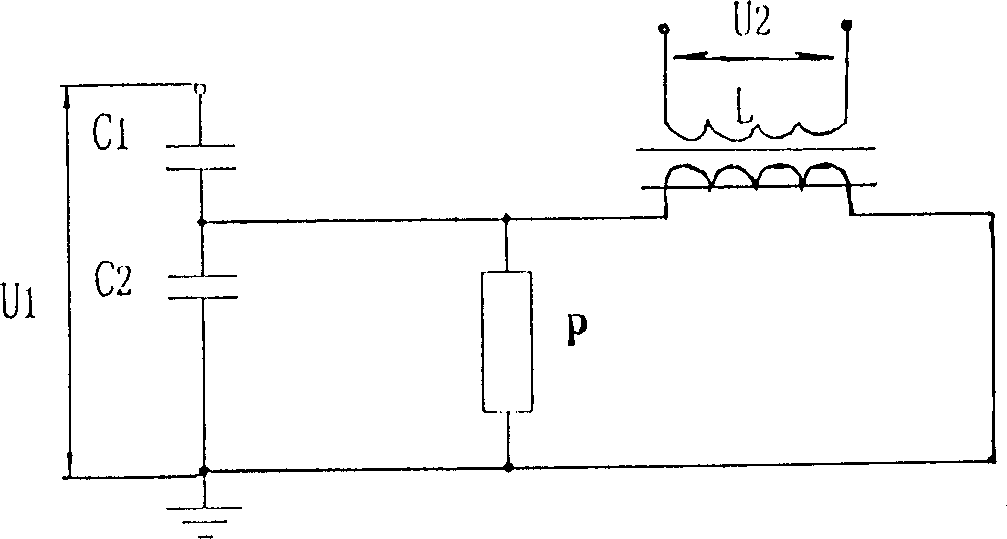
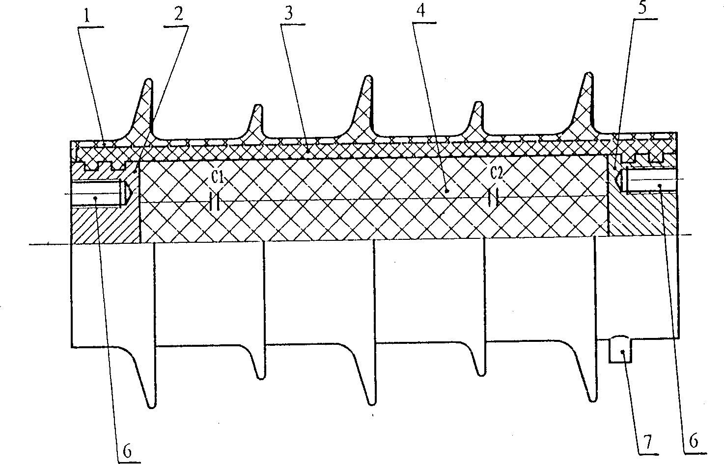
[0017] The voltage sensor consists of a capacitive divider (see Figure 1-2 ), the capacitive voltage divider has an insulating casing 1 made of silicone rubber with an umbrella skirt and an insulating cylinder 3 made of epoxy resin to form an insulating shell, the insulating cylinder is set in the insulating sleeve, and the insulating cylinder The two ends of the hole are made of rectangular threads, and the 10KV high-voltage end 2 connected to the high-voltage power grid and the fixed grounding end 5 are made of metal, which are screwed to the two ends of the insulating cylinder, and the grounding end is made into a concentric ring , so that there are holes for pouring, the high-voltage end 2 is provided with a prefabricated screw hole 6 connected to the high-voltage busbar, and the grounding end 5 is provided with a prefabricated screw hole 6 fo...


PUM


Abstract

The present invention relates to a voltage transducer, which is characterized by that it includes a capacitive divider formed of insulating shell body, high-voltage end, grounding end, series-connected capacitors of C1 and C2 and oil-free dry packing layer, in which the C1 and C2 are respectively formed of several separate metallized film capacitors which are series-parallel connected, and a secondary voltage end is led out from connected place of C1 and C2, and is parallel-connected with a reactance transformer including mounting frame and two up-and-down oppositely-arranged "C" type iron cores on which the primary reactance winding coil and secondary transformer winding coil are winded, at the same time an overvoltage protector is parallel connected between the secondary voltage end andgrounding end.

Description

technical field [0001] The invention relates to the field of high-voltage electrical appliances, in particular to a sensing mechanism for obtaining a secondary voltage source from a 10KV high-voltage power supply. Background technique [0002] The voltage sensor is used in the 10KV distribution network, which is a way to convert the 10KV power supply into 220 The current voltage transformers are all iron-core multi-coil winding transformers, which have poor insulation performance, large volume, and high cost. They are especially not suitable for outdoor use and cannot be used as high-voltage electrical appliances. insulator applications. High-voltage capacitive voltage transformers at home and abroad commonly use concentric circle capacitance screen type or one-section to multi-section bushing type coupling capacitors. Both concentric circle capacitance screens and bushing type coupling capacitors are film-paper composite media and require vacuum treatment and heat treatme...

Claims


Application Information

Patent Timeline
Patent Type & Authority Applications(China)
IPC IPC(8): G01R15/06
Inventor 周友东王德才
Owner 周友东
Why Eureka
Try Eureka